> the 50L6 is looking for a 2000 ohms load
It is not "looking for". It does not care.
If you run an ideal pentode at 110V 49mA, simple arithmetic suggests 2.245K load for best output. And at 200V 46mA a good trial fit is 4.35K. These will not be too critical.
The 50L6 is not "ideal", and we try some other loads for "best" performance and also for attractive data. The G.E. 50L6 datasheet gives 2K for 110V 49mA and 4K for 200V 46mA, for 10% THD and reasonable bias-shift from idle to roar.
http://www.mif.pg.gda.pl/homepages/frank/sheets/093/2/25L6GT.pdf
Yes, another load will reduce maximum power. See page 4. For the 200V 46mA (4.35K) condition there is little real change from 3K to 6K, and it looks like 3.5K may be insignificantly "best". Note that the curve may be misleading. It was taken with constant input level, despite distortion. A "clean" user would turn-down, get any reasonable lower THD but at lower power.
Last edited:
Star grounding is beautiful, but hard to do unless you are building a very simple circuit with very few components. You can't really "star" together twenty or thirty wires.One say this and that.. What do you think about star grounding?
")
Merlin Blencowe (Valve Wizard) has a section in his valve guitar preamp book on grounding - he points out that, beyond star grounding, we can have a "star of stars" when the circuit is too complex for a single star. The bus arrangement I described is basically a "star of stars".
If your grounding scheme works and doesn't hum, it's good...no matter who says what! There is more than one way that works.
If it sounds good, it's good!...so far the amp sounds pretty good...
Yes, it is inverted. Just like any common-cathode triode or pentode gain stage.Is the signal coming out the cascode inverted or not?
Blencowe points out that in fact a cascode of two triodes behaves a lot like a single pentode...which is one reason why I just use a pentode! Why pay for two triodes, and deal with the additional complexity of wiring them in cascode? There are cheap unpopular pentodes (and triode-pentodes) that are fun to experiment with.
Probably any of those 50L6 radio OTs will work...just make sure you use a transformer intended for a single-ended circuit. An SE transformer will usually be bigger and heavier, and have a "gap" in its magnetic circuit, so that it can tolerate the steady 50 mA or so of bias current through the 50L6....OT for this amp...
You're right that the output power will change a little with OT primary impedance. But keep in mind that doubling the power is only a 3 dB change - and that's not a very big change to the human ear. So if power goes up or down by a few percent, you won't even hear any difference at all.
(1 dB is about the same as 12% change, and a 1 dB change is barely detectable by the human ear.)
-Gnobuddy
It is not "looking for". It does not care..
Thank you so much for the clarification.
Looking at the curve I see exactly what you say, helps me a lot to make my choice!
If your grounding scheme works and doesn't hum, it's good...no matter who says what! There is more than one way that works.
If it sounds good, it's good!

I can't say anything than I agree with everything you say
The first built I did was an 18 Watt EL-84 Push Pull (point-to-point), well the guy on the other forum was laughing at me saying I would have alot of noise/hum with this 'spaghetti' wiring. In real it is not that bad, maybe I'm not a good photograph after all but anyway this amp is quiet as hell with such a killer sound (thanks to the same guys as well), for sure we have the basic thumb of rules in everything and to jump the gate sometimes brings good things.
Yes, it is inverted. Just like any common-cathode triode or pentode gain stage.
Blencowe points out that in fact a cascode of two triodes behaves a lot like a single pentode...which is one reason why I just use a pentode! Why pay for two triodes, and deal with the additional complexity of wiring them in cascode? There are cheap unpopular pentodes (and triode-pentodes) that are fun to experiment with.
Okay so I can't just take the cascode stage then put a coupling capacitor at the output.. Would it be better to have a non inverted signal to use this 'like a pedal' in front of my amps?
I have plenty of AU7/AX7 tubes, but I agree if I would have to pay an expensive price for these preamp tubes, I would do the same as you.
Probably any of those 50L6 radio OTs will work...just make sure you use a transformer intended for a single-ended circuit. An SE transformer will usually be bigger and heavier, and have a "gap" in its magnetic circuit, so that it can tolerate the steady 50 mA or so of bias current through the 50L6.
You're right that the output power will change a little with OT primary impedance. But keep in mind that doubling the power is only a 3 dB change - and that's not a very big change to the human ear. So if power goes up or down by a few percent, you won't even hear any difference at all.
(1 dB is about the same as 12% change, and a 1 dB change is barely detectable by the human ear.)
I was just wondering because when I switch for example from 4 to 8 ohms (using the switch on the back of my cab), I can truly hear a power difference, and since I saw so many OT ratios, I would say from 18:1 to 36:1, I just wanna make sure I will have 'some kind of a good match'.
I know it's not that critical, but I'm learning.
Thanks for your time and all the precious advises!
I think this is really true with grounding...there are some good rules of thumb, but there really is more than one way to do it, especially with simple audio-frequency circuits like guitar amps.we have the basic rules of thumb in everything
Sure you can, if you like. Just be sure to use a pair of resistors to attenuate the heck out of the signal from the cascode before feeding it into your main amp input. Your amp will not be happy if you feed a 150 volt (peak to peak) signal into it, and the cascode probably can put out that much.Okay so I can't just take the cascode stage then put a coupling capacitor at the output...
I suggest dividing that down to no more than 1 Vpp as a starting point. Something like 680k from the cascode output, 4.7k to ground, and feed the signal from the junction of the 680k and 4.7k to the guitar amp. If the signal is not big enough, increase the 4.7k. If the signal is too big, decrease the 4.7k.
Your ears can't hear absolute phase. So, 99.9% of the time, it makes no difference at all. There are two exceptions I can think of, when pedal phasing actually does matter:Would it be better to have a non inverted signal to use this 'like a pedal' in front of my amps?
(1) If you are using a "stereo" guitar rig, with two amps and two speakers, and you are inserting the cascode booster only in front of *one* amp, then it probably shouldn't invert. If it does, some of the bass from the two amps might cancel out.
(2)If you are planning to put two pedals in parallel and mix their outputs together, then either both should invert, or both should not invert. Otherwise, there will be unwanted signal cancellations.
I wonder how the cab is wired internally. Is only one speaker connected in the 8 ohm position, and both speakers in the 4 ohm position? If so, you can get an additional 3 dB increase in sound pressure level simply because using two speakers is more efficient than using one single speaker.I was just wondering because when I switch for example from 4 to 8 ohms (using the switch on the back of my cab), I can truly hear a power difference
Definitely a good idea, especially since transformers aren't cheap!I just wanna make sure I will have 'some kind of a good match'.
-Gnobuddy
Sure you can, if you like. Just be sure to use a pair of resistors to attenuate the heck out of the signal from the cascode before feeding it into your main amp input. Your amp will not be happy if you feed a 150 volt (peak to peak) signal into it, and the cascode probably can put out that much.
I suggest dividing that down to no more than 1 Vpp as a starting point. Something like 680k from the cascode output, 4.7k to ground, and feed the signal from the junction of the 680k and 4.7k to the guitar amp. If the signal is not big enough, increase the 4.7k. If the signal is too big, decrease the 4.7k.
Okay! Just like R8/R9 in the Real MCTube
Thank you for pointing this out to me and save my amps!!
Your ears can't hear absolute phase. So, 99.9% of the time, it makes no difference at all. There are two exceptions I can think of, when pedal phasing actually does matter:
(1) If you are using a "stereo" guitar rig, with two amps and two speakers, and you are inserting the cascode booster only in front of *one* amp, then it probably shouldn't invert. If it does, some of the bass from the two amps might cancel out.
(2)If you are planning to put two pedals in parallel and mix their outputs together, then either both should invert, or both should not invert. Otherwise, there will be unwanted signal cancellations.
Oh right, sometimes we use to 'naturally' know things, I'm in an extensive learning right now and those things could be confused, so I need a psy
Just kidding.. I've experience this while hooking speakers on the wrong polarity.. I thought an inverted signal would be thin, but it's really a cancellation effect.
I wonder how the cab is wired internally. Is only one speaker connected in the 8 ohm position, and both speakers in the 4 ohm position? If so, you can get an additional 3 dB increase in sound pressure level simply because using two speakers is more efficient than using one single speaker.
You are correct..
I have 2 speakers which are the same but one is 8ohm and the other 16, will compare with an a/b switch.
I'm curious like that
Your advises are highly appreciated Sir!
The 220uF 75V cap next to the 68R resistor is drawn with its polarity reversed.then I found this schematic using only one 50L6 (from Tino Zottola's book) :
http://www.kirtland.com/guitar1/guitar1/MA1_files/50L6_Amp-1.gif
Good catch! I totally missed that.The 220uF 75V cap next to the 68R resistor is drawn with its polarity reversed.
-Gnobuddy
The 220uF 75V cap next to the 68R resistor is drawn with its polarity reversed.
Thank you!
Hey guys!
Did tests and thought about sharing the results with you. I found one of these 70V line transformer in my junk box and remembered having seen some people using that in tube amps.
After some googling, well you know, one says it will work well in some Push Pull designs, depending of a balanced center tap or not, others say it won't with SE designs, that it will built heat because of a missing air gap.
The conclusion, a more than ever confused poor little man! So I thought what the heck, why not give a try for real!
First of all, my 70V line transformer looks like just the one shown in the picture but rated at 10W. At the primary it has (10W - 5W - 2.5W - 1.25W - 0.62W) and the usual (4 ohms - 8 ohms - C) at the secondary. I know for sure that it is suggested for a 50L6 tube to see a 2k load impedance, but hey I don't want to damage my (test)amp, a typical 12ax7-35C5-50C5, or kill my tubes, so my courage and I did some learning/maths.
The ohm law says
W = E*I = I = E/R
Therefore W = E²/R
I found that a 70V line transformer is 'in reality' 70.7V, here's what I did:
70.7 X 70.7 = 5000 roughly
So W = 5000/R or R = 5000/W
Then 5000V/2.5W = 2000 ohms
Huh! Exactly what I'm looking for -> 2000 ohms !
I remember how to find the turns ratio but just to have a 'physical look' I took my variac on 10 VAC and hooked the primary (C and 2.5W wires), got 0.455 VAC at the secondary (4 ohms and C wires)
So 10/0.455 = 22:1 turns ratio
Okay, let's do it!!
Well, after having removed the original OT (wires) and swapped this transformer in the amp, was very happy to hear the sound coming from the speaker, having played for about roughly an hour cranked (attenuated), here's the conclusion:
1 - The sound is 'slightly' different but surely not in a bad way, as good as the original OT I would say.
2 - The transformer stayed cold as ice, all the way.
I think of using this $3 puppy in my 50L6 desing I am working on the parts list right now, will also have to modify a bit in the preamp section, and I'm ready! Do not hesitate to correct me if I'm wrong, because the good sound's the only thing I'm sure about right now
Thanks all!
Did tests and thought about sharing the results with you. I found one of these 70V line transformer in my junk box and remembered having seen some people using that in tube amps.
After some googling, well you know, one says it will work well in some Push Pull designs, depending of a balanced center tap or not, others say it won't with SE designs, that it will built heat because of a missing air gap.
The conclusion, a more than ever confused poor little man! So I thought what the heck, why not give a try for real!
First of all, my 70V line transformer looks like just the one shown in the picture but rated at 10W. At the primary it has (10W - 5W - 2.5W - 1.25W - 0.62W) and the usual (4 ohms - 8 ohms - C) at the secondary. I know for sure that it is suggested for a 50L6 tube to see a 2k load impedance, but hey I don't want to damage my (test)amp, a typical 12ax7-35C5-50C5, or kill my tubes, so my courage and I did some learning/maths.
The ohm law says
W = E*I = I = E/R
Therefore W = E²/R
I found that a 70V line transformer is 'in reality' 70.7V, here's what I did:
70.7 X 70.7 = 5000 roughly
So W = 5000/R or R = 5000/W
Then 5000V/2.5W = 2000 ohms
Huh! Exactly what I'm looking for -> 2000 ohms !
I remember how to find the turns ratio but just to have a 'physical look' I took my variac on 10 VAC and hooked the primary (C and 2.5W wires), got 0.455 VAC at the secondary (4 ohms and C wires)
So 10/0.455 = 22:1 turns ratio
Okay, let's do it!!
Well, after having removed the original OT (wires) and swapped this transformer in the amp, was very happy to hear the sound coming from the speaker, having played for about roughly an hour cranked (attenuated), here's the conclusion:
1 - The sound is 'slightly' different but surely not in a bad way, as good as the original OT I would say.
2 - The transformer stayed cold as ice, all the way.
I think of using this $3 puppy in my 50L6 desing
I am working on the parts list right now, will also have to modify a bit in the preamp section, and I'm ready! Do not hesitate to correct me if I'm wrong, because the good sound's the only thing I'm sure about right now Thanks all!
And that's the most important thing!the good sound's the only thing I'm sure about right now
I almost made this exact suggestion to you (using a 70V audio line transformer), because I knew you would easily get the 2000 ohms you wanted from the 2.5W tap. But I have never used one myself, and I've read the same concern as you about using an un-gapped transformer with an SE output, so I kept my fingers off the keyboard.
That said, I used to be on an Australian guitar forum, and there were a few people there who reported successfully using cheap audio line transformers in SE designs. It seems you have confirmed what they found.
There is one other concern to keep in mind with these little 70V transformers - we don't know how good the insulation between primary and secondary windings is. It is possible they used the cheapest thing they could find (paper or plastic tape) and it happens to be good for a few hundred volts. But we don't know.
Translation: Just to be on the safe side, don't touch either of the speaker leads when the amp is powered on. Try to arrange things so it is impossible to touch the speaker leads when the amp is powered on, just in case the audio line transformer insulation "flashes over" and the B+ voltage gets through to the speaker side.
If you're planning for this to be a combo amp, that probably makes it reasonably safe if you solder the speaker wiring in place and insulate all exposed ends with heat-shrink tubing.
This is turning into an interesting, unusual project. What fun!
-Gnobuddy
OTOH, there are reports of sucessful usage of transformers of that kind in PP amplifiers that operate at higher plate voltages!
Best regards!
Best regards!
An un-gapped E-I core will "work" in an SE amp, if it is about 4X the size of an optimum gapped core. On a flat earth, this is dumb economics. On our earth, today, "big" 70V trannies are much cheaper than small SE trannies, so not a dumb idea.
The common 70V trannies are usually poor bass. Actually they do OK when fed from a large power amplifier. When fed from a tube they may be bass-shy. Up-sizing another 2X may help a bunch.
Yeah, a "10W" core may be fine for ~~1W 50L6 in guitar-amp duty.
The common 70V trannies are usually poor bass. Actually they do OK when fed from a large power amplifier. When fed from a tube they may be bass-shy. Up-sizing another 2X may help a bunch.
Yeah, a "10W" core may be fine for ~~1W 50L6 in guitar-amp duty.
From what I know, it seems that Paul Cambie, Grant Wills, and Roly Roper (all from Australia) seem to be the three people who got the ball rolling.OTOH, there are reports of sucessful usage of transformers of that kind in PP amplifiers that operate at higher plate voltages!
Cambie seems to be the guy who pioneered the idea that 70V line transformers could work as valve output transformers ( http://home.alphalink.com.au/~cambie/6AN8amp/M1115.htm ).
Grant Wills seems to then taken Cambie's idea and built a proof-of-concept amplifier (the link you posted.)
Meantime Roly Roeper was trying to figure out how to create a budget valve guitar amp design for beginners to build ( AVA100project ); he had the idea to use a voltage multiplier to get the B+ voltages from inexpensive off-the-shelf power transformers designed for solid-state applications. When Roper heard of Paul Cambie's audio line transformer idea, he leapt at it: Cheap Output Transformers
IMO the combination of those two ideas (using easily available low-voltage power transformers along with voltage multipliers, and using 70 V audio line transformers for OTs) is really clever, and dramatically lowers the cost of building a valve guitar amp.
-Gnobuddy
Thank you for these supplementary informations, Gnobuddy !
I think that some of these 100V line matching transformers could also be worth a try with the amplifier described in Norman Crowhurst's Radio Electronics paper »High Power Twin-Coupled Amplifier« we've discussed several times before.
Best regards!
!I think that some of these 100V line matching transformers could also be worth a try with the amplifier described in Norman Crowhurst's Radio Electronics paper »High Power Twin-Coupled Amplifier« we've discussed several times before.
Best regards!
Lovely for Hi-Fi (i.e. very linear), or lovely for electric guitar (i.e. quite nonlinear with lots of tasty 2nd-harmonic distortion?Which is handy, because the 50L6 types make lovely triodes
)The attached image shows a very non-linear triode that I think sounds quite good for e-guitar. Just look at the enormous difference in length between the green and pink half-cycle swings. This is no 12AX7!
-Gnobuddy
Attachments
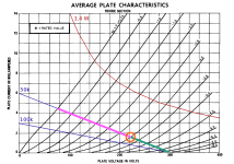
The 50L6 is a 6W6 with a 50 volt heater. I have been experimenting with the 6W6 types for HiFi use and they are indeed quite clean in triode mode. Want to dirty them up a bit, just raise the value of the screen stopper resistor.
Gnobuddy, it took my about 8 miliseconds to figure out where those triode curves came from. Both of it's suggested uses do not require good linearity, so maybe it was optimized for something else, or it's parameters were specified explicitly by a TV set manufacturer.
Gnobuddy, it took my about 8 miliseconds to figure out where those triode curves came from. Both of it's suggested uses do not require good linearity, so maybe it was optimized for something else, or it's parameters were specified explicitly by a TV set manufacturer.
- Status
- This old topic is closed. If you want to reopen this topic, contact a moderator using the "Report Post" button.
- Home
- Live Sound
- Instruments and Amps
- 50L6 guitar amp