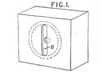
Yes, Briggs begins by looking at the vertical slot diffuser on its own and attributes it to Kolster-Brandes Ltd. Looking them up, I find that this company utilised a patented slot diffuser in their LG40 radio.I'd be surprised if he hadn't tried the slot by itself.
LG40 Radio Kolster Brandes Ltd. KB, K.B., ITT; Foots Cray; G
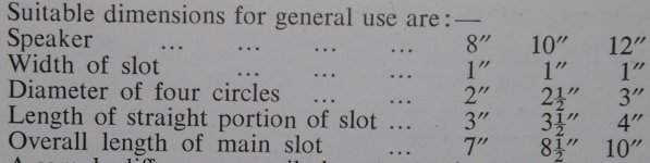
Briggs says that "The length of the slot should be the same as the piston diameter of the cone, the width being determined according to the wavelength; it is most effective when it is less than the wavelength. With a 5" speaker, a slot 3" long and 3/4" wide is about right."
He notes that "The use of this diffuser greatly reduces the difference between axis and off-axis results."
However, he continues: "but with a single speaker covering the entire range, there is severe obstruction at low frequencies. This is largely overcome by altering the shape of the slot and adding extra holes."
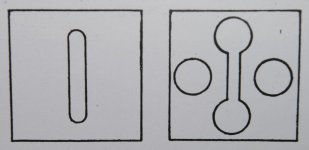
I shall post the altered shape and dimensional details later.
Here's the patent and an attached image of the Kolster Brandes vertical slot diffuser:
Espacenet -
Bibliographic data
Espacenet -
Bibliographic data
Attachments
Thanks for posting the template!
If high frequencies come out of those holes, the sound waves will inevitably interfere and cause treble beaming and lobing of the polar response.
I suspect the key to this slot + holes diffuser is the big, soft, thin, floppy paper cone used on speakers in Brigg's time (and still used in guitar speakers today.) Cones like this do not move as rigid pistons at high frequencies, and most of the treble is only radiated from the centre. The outer edges tend to only vibrate at the bass and midrange end of the spectrum.
This would mean that mostly bass and midrange sound waves emerge from the round holes. Those longer wavelengths don't interfere severely even across the diameter of a 12" speaker.
Meantime, high frequencies (well, relatively high, given the limitations of this type of speaker) would mostly emerge from the central slot. The treble dispersion would be controlled by the slot width, as Briggs said.
The idea seems well worth trying, and I'll put it on the list of stuff I should really do one of these days.")
-Gnobuddy
I figured the holes were there to prevent trapping air in front of the cone at low frequencies. But the thing that was bothering me was the two side-by-side holes near the middle of the slot."...there is severe obstruction at low frequencies. This is largely overcome by altering the shape of the slot and adding extra holes."
If high frequencies come out of those holes, the sound waves will inevitably interfere and cause treble beaming and lobing of the polar response.
I suspect the key to this slot + holes diffuser is the big, soft, thin, floppy paper cone used on speakers in Brigg's time (and still used in guitar speakers today.) Cones like this do not move as rigid pistons at high frequencies, and most of the treble is only radiated from the centre. The outer edges tend to only vibrate at the bass and midrange end of the spectrum.
This would mean that mostly bass and midrange sound waves emerge from the round holes. Those longer wavelengths don't interfere severely even across the diameter of a 12" speaker.
Meantime, high frequencies (well, relatively high, given the limitations of this type of speaker) would mostly emerge from the central slot. The treble dispersion would be controlled by the slot width, as Briggs said.
The idea seems well worth trying, and I'll put it on the list of stuff I should really do one of these days.
-Gnobuddy
Thanks for your description of the action of the diffuser - extremely well analysed!
Without measuring facilities like, or superior to, the ones available to Briggs, it would not be possible to quantify the effects of the diffuser.
Perhaps some interested party will give the diffuser a try, if only to share their subjective results.
Or perhaps some entrepreneur will fashion one out of perspex and put it on the market for £300!
These days you can do a lot with an old PC, some free software, and a relatively inexpensive microphone.Without measuring facilities like, or superior to, the ones available to Briggs, it would not be possible to quantify the effects of the diffuser.
But I am on a tight budget, there is only so much time in a day, and there are too many interesting roads to walk down all of them.
That could happen.Or perhaps some entrepreneur will fashion one out of perspex and put it on the market for £300!
I'm really curious what goes on in the minds of the people selling the "Deeflex". The concept is childishly simple, and even the brand-name is idiotic. What on earth makes them think it's worth the price they're asking?
-Gnobuddy
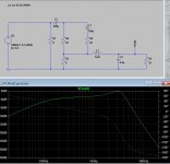
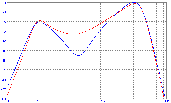
This time there is a 40 dB/octave rolloff above 3 kHz, along with the characteristic slowly rising response from 300 Hz to 3 kHz. The peak at around 3 kHz is itself higher Q, and more like the peak in an actual guitar speaker response.
The downside is that this version uses a 1 mH inductor to make the improvements possible. The current through the little inductor peaks at about 35 mA RMS, so a relatively small ferrite-cored inductor will probably do the job.
-Gnobuddy
I've been playing around with the passive filter circuit and have come up with the attached.
Not much has really changed except the addition of a capacitor in the signal path to filter the lower frequencies. (Yeah, probably sacrilege!). The shape looks more like the speaker graph provided earlier.
I'm sure those enlightened ones amongst us are probably laughing, shaking their heads and primed to tell me what the rookie error I made is (please do!).
I ran an acoustic guitar recording through the filter in LTSpice and output to .wav, then played A/B. The filter softens the tones out quite nicely, maybe a little too much. I'd like to try for real though and hear what it is like with an instrument.
Any chance of a sanity check to see if this circuit is ok to run? I intend to use a ~5W output, 8Ohm OPT winding. I left R1 at 8 Ohm as I have a 50w 8Ohm to hand.
Attachments
I think we're fresh out of enlightened ones.I'm sure those enlightened ones amongst us...
We're all groping around in the dark here. The blind leading the blind. But at least we're moving in some direction, and hopefully we will all eventually end up a bit more knowledgeable.
I expect most of the people who actually know what they're doing, work for large music electronics corporations with signed non-disclosure agreements in place, and a team of lawyers on retainer, waiting to pounce. Those guys and gals are not about to tell us how guitar speaker emulation is done.
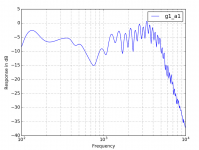
A while ago, I stumbled across the attached image - a frequency response plot of a Zoom G1on, one of those little buzzy digital guitar amp / FX simulator pedals. Clearly this is an attempt at speaker emulation, and a rather ugly-looking one.
It looks as though they used a microphone to measure the frequency response of a speaker/cab in a room (not anechoic chamber), and then used DSP to re-create the measured response, complete with numerous dips and peaks that are actually not from the speaker at all, but from acoustic reflections and interference in the room.
I don't think this is the right way to do it. In my experience, jagged responses like this tend to cause ear-fatigue, probably because our ear/brain doesn't hear the same way as a microphone. Our brains can pick out delayed reflected sound from direct line-of-sight sound, and interpret it as "I'm in a room about this big", rather than just hearing a bunch of jaggies in a frequency response.
But if we ignore the trees and focus on the forest, the Zoom filter does have the same overall features we've been discussing - deep bass is rolled off, there is a bass peak, a rise to around 3 kHz, and a steep fall beyond that.
There also appears to be an 800 Hz notch, which is exactly where I use a graphic EQ pedal to put a slight notch if I want my guitar to sound smoother, less harsh, less midrangey.
Agreed.I'd like to try for real though and hear what it is like with an instrument.
By the way, is the amp you're building intended for clean acoustic guitar only? Because you can certainly use a wider frequency response with clean acoustic guitar than you can with distorted electric guitar.
I suggest using LTSpice to check the input impedance of the circuit, i.e. the load presented to the driving amplifier. You can insert a 1 milliohm resistor in series with the input, plot current through it, then "add trace" and display input voltage divided by input current.Any chance of a sanity check to see if this circuit is ok to run?
<snip>
I left R1 at 8 Ohm as I have a 50w 8Ohm to hand.
My concern is that with R1 at 8 ohms, overall impedance may drop down to nearly 4 ohms at some higher frequencies (imagine all capacitors as short circuits, so R1, R2, R4 all end up virtually in parallel.) I think that's why I ended up bumping R1 to 15 ohms.
-Gnobuddy
Attachments
Thanks for your help Gnobuddy.
I have run the LT as you suggested (thanks, I've learnt a new trick) and if I am reading it right, the impedance will drop to around 4.8 ohms.
I do have a 4 ohm tap on the OPT that could be usable, but I would rather stick with the 8 ohm for now.
This particular amp would be used predominantly with electric, although there would probably be some acoustic as well.
But now you mention it.... I'm thinking of making the frequency response selectable via a switch for Acoustic / Electric.. Jumping ahead of myself, but I think that might be an idea to follow up on later.
I have run the LT as you suggested (thanks, I've learnt a new trick) and if I am reading it right, the impedance will drop to around 4.8 ohms.
I do have a 4 ohm tap on the OPT that could be usable, but I would rather stick with the 8 ohm for now.
By the way, is the amp you're building intended for clean acoustic guitar only? Because you can certainly use a wider frequency response with clean acoustic guitar than you can with distorted electric guitar.
This particular amp would be used predominantly with electric, although there would probably be some acoustic as well.
But now you mention it.... I'm thinking of making the frequency response selectable via a switch for Acoustic / Electric.. Jumping ahead of myself, but I think that might be an idea to follow up on later.
Attachments
Thanks for those links.
I'm looking at taking the output side of the amp and passively filtering that for headphone use rather than altering the input side.
The main goal is to be able to plug a set of headphones into the amp, that disconnects the speaker and safely loads the 6V6, as well as attenuating the output. (Probably an inefficient way of doing things!) The filtering is to make the output sound good when presented by the flat / wide frequency response headphones.
The main goal is to be able to plug a set of headphones into the amp, that disconnects the speaker and safely loads the 6V6, as well as attenuating the output. (Probably an inefficient way of doing things!)
There's a few schematics out there for this (I think Marshall and Fender both provide this option) or you could just leave 100ohms across the OPT at all times
Oh, Yet Another Speaker Simulator here
If you're really clever you'd make the simulator passive and dump all the extra watts in the resistors therein, avoiding the need for any more gain stages to drive the head phones.
Last edited:
There is a design mistake in that one - the low-pass filters are fed from the high (and variable) source impedance of the gain potentiometer, instead of from the fixed, very low source impedance necessary for the filter to work properly. This means the frequency response will change considerably with the gain setting.Oh, Yet Another Speaker Simulator here
The problem can be fixed by using a buffer stage between gain control and the input of the first low pass filter.
I really like the amount of adjustability in this design, though. Tweak to taste, much better than one-size-fits-all.
The Runoffgroove filter suffers from two different problems. Firstly, it has an extremely soggy frequency response curve, with a very gradual initial treble roll off. This is because they just ran one passive RC low pass filter into a second one, instead of using controlled positive feedback to raise the Q of the low pass filter.
Secondly, the Runoffgroove sim only has a 2nd order low-pass, even though it is relatively complex, with several active devices.
Like the Runoffgroove cab sim, the passive headphone filter currently being discussed on this thread is only second-order (a real speaker appears to be 4th order to start with, steepening to 6th or 8th order as frequency continues to rise.) However, in the current design, I used an inductor to raise the Q, so you do get a much steeper initial HF roll off than the Runoffgroove sim can provide.
Earlier in this thread I also posted an active filter design which has a 4th order HF roll off. However, it does have a lot of components in it, and some need to be 1% or 2% tolerance.
-Gnobuddy
Last edited:
With the increasing popularity of guitar cab simulator pedals, the speaker cab which reproduces an emulation should have no character of its own.Originally posted by Gnobuddy > "Those guys and gals are not about to tell us how guitar speaker emulation is done."
The days of individually voiced loudspeaker cabinets may be numbered. They are already being replaced by Full Range, Flat Response (FRFR) loudspeaker designs.
Soon, the only guitar speaker frequency response curve that may concern us is a flat one!
http://aus.matrixamplification.com/fr212-passive.html
I have been headed in that direction for a while, for a very simple reason: price! I can find nominally flat-response boombox speakers for a few bucks in local thrift store, but "real" guitar speakers cost anywhere from $50 to $300. I don't need the tremendous SPL capability of the real guitar speakers, so there is a lot of incentive to use the affordable alternatives.Soon, the only guitar speaker frequency response curve that may concern us is a flat one!
There are also very inexpensive true P.A. (paging / background music) "full range", dual-cone speakers available. Some of those have sensitivities up around 95 dB/W @1m, comparable to a guitar speaker, but at half to one-tenth the price (Parts Express has one under $10 USD). But they have nominally flat frequency responses, rather than intentional guitar-speaker weirdness.
There is an elephant in the room we need to ignore when it comes to flat-response speakers: you cannot allow the power amp to ever be overdriven, otherwise it will generate tons of ugly high frequencies which will be fed directly to your flat-response speaker, which will reproduce them accurately and send you (and your audience) running for cover with fingers in ears.
That elephant stays politely on the sidelines if you have a 500-watt class D power amplifier, and don't demand insane loudness levels. But for those of us who might use a few-watt valve amp as the power amp, the elephant might come charging right at you, trunk up, ears out, and trumpeting angrily.
So I think it might also be an interesting project to try to design a passive 4th-order low-pass filter to go between power amp and speaker. Basically just like the woofer part of a regular Hi-Fi crossover network, except with a much higher "Q", tuned to peak at around 3 - 3.5 kHz and then fall rapidly.
-Gnobuddy
If we ignore the elephant does it become irrelephant?There is an elephant in the room we need to ignore when it comes to flat-response speakers . . .

Very much agree on trying to use cheap speakers made by the millions, but in that case keep it simple , instead of extending frequency response into undesirable realms and then make a complex/expensive filter to tame it, just amputate the offending part
Carefully cut the dual/whizzer cone away with a sharp knife and if you wish to dull remaining "still higher than you like" response, add a ring/bead of adhesive, from light Epoxy to evaporated/thickened Nitro/universal car type lacquer (or nail enamel) around the voice coil, filling the nice V shaped "valley" where it joins the cone.
Congratulations, you have just turned a PA/background music speaker into a little Guitar type one.
You basically turn this:
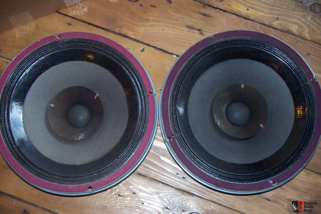
into this:
, instead of extending frequency response into undesirable realms and then make a complex/expensive filter to tame it, just amputate the offending part Carefully cut the dual/whizzer cone away with a sharp knife and if you wish to dull remaining "still higher than you like" response, add a ring/bead of adhesive, from light Epoxy to evaporated/thickened Nitro/universal car type lacquer (or nail enamel) around the voice coil, filling the nice V shaped "valley" where it joins the cone.
Congratulations, you have just turned a PA/background music speaker into a little Guitar type one.
You basically turn this:
into this:
Speaker circumcision - does it increase sensitivity?. . . just amputate the offending part
- Status
- This old topic is closed. If you want to reopen this topic, contact a moderator using the "Report Post" button.
- Home
- Live Sound
- Instruments and Amps
- Princeton Headphone Mod. This one ok?