I want to add a headphone output to a 5F2A Princeton build that I've nearly finished. Output power will probably be in the range of 5 watts or so.
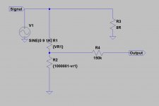
My plan is to use a 1meg pot for volume control and a 150k series resistor all in parallel with an 8 ohm power resistor to protect the OPT.
I'm thinking of using a switch to swap between the speaker jack and the headphone jack or should I just use the breaking contact to switch whenever a headphone jack is plugged in?
Would this work at all?
Thanks!!
BTW - Would the OPT be hurt if the speaker jack is vacant when the amp is switched on? I notice that the secondary of the output transformer is connected short to ground when the jack is unplugged. To protect the amp, wouldn't it be better to connect to ground via a power resistor rather than short?
Attachments
Last edited:
What is the impedance of your headphones? Any less than 150k and they won't work!
If your headphones are less than 32R impedance, plugging them into the LS jack will be fine as your ears will not allow too much volume but be careful of your ears!
OR make R1 = 22R 2W
R2 = 100R 2W
R3 10R 5W
R4 = 22R 1/2 W
If your headphones are less than 32R impedance, plugging them into the LS jack will be fine as your ears will not allow too much volume but be careful of your ears!
OR make R1 = 22R 2W
R2 = 100R 2W
R3 10R 5W
R4 = 22R 1/2 W
Thanks Jon,
Guessing the headphones impedance will be 32ohm. Mine are 38ohm but this amp isn't for me.
So just use a potential divider instead of extra 1M pot and control via the existing volume pot?
I've already got an 8ohm 50w for R3. Might be a bit overkill but it should work.
Guessing the headphones impedance will be 32ohm. Mine are 38ohm but this amp isn't for me.
So just use a potential divider instead of extra 1M pot and control via the existing volume pot?
I've already got an 8ohm 50w for R3. Might be a bit overkill but it should work.
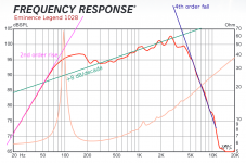
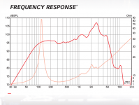
Guitar speakers almost always have a frequency response that rises from around 300 Hz to around 3 - 3.5 kHz, then falls like a rock. The fall usually starts like a 4th order RC filter, at 24 dB/octave or 80 dB/decade, and soon steepens to 36 dB/octave or 48 dB/octave before falling into the noise floor of the measurement electronics.So just use a potential divider instead of extra 1M pot and control via the existing volume pot?
Meantime, even cheap headphones will usually be relatively flat to out beyond 15 kHz, and maybe well beyond 20 kHz.
My ears tell me that what the guitar produces above 5 kHz sounds unpleasantly harsh for clean tones, and extremely unpleasant when overdriven.
Getting the signal level and output impedance right for the headphones is relatively easy. Fixing the harsh and maybe painful tone you will then hear through them is harder.

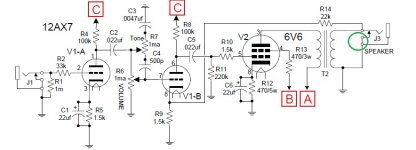
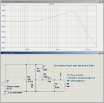
I'm attaching a couple of pics based on the manufacturer's datasheet frequency response for an Eminence legend 1058, and also a headphone attenuator design that might be worth a try, as it makes at least a crude attempt to resemble a guitar speaker, rather than a flat-frequency Hi-Fi speaker.
And I do mean crude - the real speaker falls off at 80 dB/decade above 4 kHz or so, while the headphone adaptor only manages 20 dB/decade. Still, that's probably better than doing nothing at all to limit those unpleasant, ear-damaging, harsh high-frequency nasties from an overdriven guitar amp.
The attenuator is designed to deliver around 4 mW into 32 ohm headphones at the frequency peak. Many of these headphones seem to have 100 dB/mW or more sensitivity, so 4 mW might produce 106 dB SPL or more at your ear, depending on the headphones.
That is more than loud enough to cause permanent hearing damage, so please set volume levels with caution...or make the 10 ohm load into a voltage divider (eg 3.9 ohms + 3.9 ohms to drop voltage by 6 dB), and feed the rest of the headphone attenuator from that.
Warning, this attenuator design is untried. You might hate it. It might steal your breakfast, or try to bite your ankles. I take no responsibility for any of those possible outcomes.
-Gnobuddy
Attachments


Last edited:
Galu - thank you! It seems the combination of LTSpice and a streak of perfectionism is a dangerous one.
Refinements? We can do a lot better if we're willing to make an active filter. This lets us come pretty close to what I think are the essential characteristics of a guitar speaker frequency response - not the little wiggles and peaks, but the broad trends of the frequency response curve.
One of my goals is to get good valve guitar amp tone without having to haul around the weight and bulk of an actual valve guitar amp. I think this might be possible with a combination of a small valve-based guitar preamp, and a guitar speaker emulation filter. The output of the filter would go into the P.A. system. (It could, of course, drive a small headphone amp instead.)
I figured the emulation filter would be the easier part to design. The attached images are what I've come up with so far.
I should add that I've deliberately avoided op amps, because I think they sound harsh in guitar preamps. No woo-woo explanations needed, I think the problem is that op amps are precise and accurate and clip harshly - so they either precisely reproduce the huge initial transient when you pick a guitar string, or clip it harshly. Either way, the result sounds harsh.
Meantime, a few imprecise, inaccurate, mushy vacuum triodes squash that transient relatively softly, making the guitar sound much better. Single BJT stages are not as squishy-soft as vacuum triodes, but certainly squishier than a precision op amp...
-Gnobuddy
Attachments

Thanks Gnobuddy!
Some great ideas for me to play with.
I agree that the output would sound pretty crappy because of the amp's frequency response so filtering the HP to make it sound better is a really good idea.
I'm trying to keep things relatively simple so I'll start off by playing with your first circuit and see how it goes
Just gotta finish the amp first.. ;-)
That is more than loud enough to cause permanent hearing damage, so please set volume levels with caution...or make the 10 ohm load into a voltage divider (eg 3.9 ohms + 3.9 ohms to drop voltage by 6 dB), and feed the rest of the headphone attenuator from that.
Good idea. I might add a series pot to the divider to allow for fine tuning the volume limit to particular headphones.
Haha sounds like my kids!
I like that idea.I might add a series pot to the divider to allow for fine tuning the volume limit to particular headphones.
Using a 10 ohm rheostat as the load resistor would also work. But the only 10 ohm rheostats I can find in North America cost $60 (CAD) each now.
Those are old NOS Ohmite rheostats, which is probably why they're now priced like jewelry. I would be happy with a Chinese-made contemporary part, but there doesn't seem to be such a thing. Not enough demand in these days of MOSFET power control, I'm guessing.
Inspired by our cats (the breakfast part), and a friends bad-tempered little dog (the ankle-biting part).Haha sounds like my kids!
-Gnobuddy
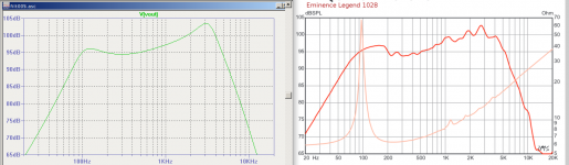
This passive headphone attenuator / guitar speaker emulation filter does a little bit better than my previous (passive) attempt.
This time there is a 40 dB/octave rolloff above 3 kHz, along with the characteristic slowly rising response from 300 Hz to 3 kHz. The peak at around 3 kHz is itself higher Q, and more like the peak in an actual guitar speaker response.
The downside is that this version uses a 1 mH inductor to make the improvements possible. The current through the little inductor peaks at about 35 mA RMS, so a relatively small ferrite-cored inductor will probably do the job.
-Gnobuddy
Attachments
I would love to hear of anything interesting your son has learned in this area. This is a big area of interest for me as well, both as a matter of curiosity, and as the only systematic way to make any progress in the design of guitar electronics.I'm passing this design development onto my son who has an interest, not only in playing the electric guitar, but also in explaining the physics which underpins the way it sounds.
One of the questions in my mind is this: published guitar speaker frequency responses were almost certainly measured directly on-axis. But real guitarists avoid listening on-axis, where the sound is often brutally bright and "ice-picky". Instead, we usually aim the guitar amp at the back of our calves, and listen with ears that are four or five feet higher.
Similarly, when we record guitar speakers, the microphone is rarely aimed directly on-axis at the centre of the speaker, because that typically produces a harsh and too-bright sound.
So the question is, what is the guitar speaker frequency response like at a more typical listening position?
A typical 12" guitar speaker is enormous compared to a proper Hi-Fi tweeter which is rarely much bigger than 1". Not surprisingly, then, guitar speakers are notorious for "beaming" treble into a tight beam. This means we can expect drastic changes to the off-axis treble response.
But how drastic? Does the rolloff above 3 - 4 kHz move down to 2 kHz? To 1 kHz?
A 2kHz upper frequency limit might sound absurd, but consider this: The diameter of a 12" speaker is already bigger than the half-wavelength of a surprisingly low 600 Hz sound wave in air at normal room temperature and pressure. In other words, we can expect treble beaming to already be occurring to some degree by this rather low frequency.
What we need is some decent guitar speaker frequency response measurements made well off-axis. I don't yet have the right equipment to make them myself, and I haven't really found any suitable ones online.
(There is lots of online information about the directionality of Hi-Fi speakers, and several decades of effort have gone into tweeter and crossover network and cabinet design to optimize and control it. Ironically, I've had much less luck finding similar information about guitar speakers, which suffer a lot more from the same problem.)
I expect the off-axis frequency response of guitar speakers will be a major factor in the proper design of a headphone attenuator like this one. You can't move off-axis from the headphones, they're clamped to your head! So the on-axis headphone response better not be as harsh as the on-axis response of a guitar speaker.
-Gnobuddy
This is NOT my son, but he has been asked by the company if he will discuss the physics behind this rather expensive solution to beaming.A typical 12" guitar speaker is enormous compared to a proper Hi-Fi tweeter which is rarely much bigger than 1". Not surprisingly, then, guitar speakers are notorious for "beaming" treble into a tight beam. This means we can expect drastic changes to the off-axis treble response.
I presume you are aware of it?
YouTube
Deeflexx H!1 Edition – Thomann UK
I wasn't, thank you for the link. However I am more than a little skeptical, and will give the advertising claims no credence until I see a comprehensive set of polar response curves made with a good measurement microphone over a wide range of frequencies in an anechoic, or quasi-anechoic measurement chamber. If the magic piece of plastic really solves treble dispersion problems, show us the data!
Will we ever see those curves? I'm not holding my breath.
By the way, about six months ago, you and I were both participants on a thread about guitar speaker dispersion, and I mentioned G.A. Brigg's attempts to widen speaker dispersion using a conical reflector. You pointed out Briggs had published that book in 1948. Seventy years ago, now.
Seventy years of trying to fix the poor treble dispersion from large-diameter speakers used over too wide a frequency range - and evidently nobody has come up with a compelling solution, otherwise it would have been in use already.
The Hi-Fi world moved on long ago, finding the only solution that actually works: use a small-diameter tweeter for the high frequencies.
Recently I have been wondering about that +8 dB/decade rising treble response region that many guitar speakers exhibit. What is the physical mechanism behind this? I speculate that it might be the progressive narrowing of the sound pattern, throwing the same number of acoustic watts into a smaller and smaller area as the frequency rises from roughly 300 Hz to 3 kHz, and so producing more SPL in areas immediately in front of the speaker (and less SPL well to the sides.)
In other words, it might be that the lousy treble dispersion of guitar speakers is unavoidable, in order to generate the expected frequency response.

-Gnobuddy
That is one of the clues that this product isn't aimed at rational buyers.$550 for a piece of shaped plastic??
Mpingo discs or Ultra Diamond Resonators, anyone? The Magic of Mpingo
-Gnobuddy
I've built more than a few widgets like this over the years. In my experience, they never work well, and usually introduce new problems of their own.
But for anyone wanting to try - a small shallow plastic bowl from the dollar-store and a strip of wood longer than the speaker diameter is all you need to make a DIY "beam blocker".
-Gnobuddy
That's precisely what I told my son, and that's why he hasn't yet taken on the Deflexx challenge!I will give the advertising claims no credence until I see a comprehensive set of polar response curves made with a good measurement microphone over a wide range of frequencies in an anechoic, or quasi-anechoic measurement chamber. If the magic piece of plastic really solves treble dispersion problems, show us the data!
Regarding the book 'Loudspeakers', Briggs discusses high frequency beaming in chapter 15.
He says that one of the simplest ways of spreading a beam and reducing peaks at 1 to 5kHz is to fit a slot diffuser in front of the cone.
The diffuser for a single wide range speaker consists of a pattern of four circles surrounding a vertical slot. I can photograph and post the pattern if you consider it worthwhile, and can also include the dimensions for 8", 10" and 12" speakers. However, we may not want to reduce the loudspeaker peaks at the same time as spreading the beam!
A sample diffuser can be cut out of cardboard for testing purposes. If the effect meets with approval, a permanent diffuser can be made with 1/4" or 3/8" plywood.
Tests with a lively 8" speaker showed that the diffuser was very effective in reducing the beam effect on-axis in the range 2kHz to 6kHz.
Good for you! (And for him!)That's precisely what I told my son, and that's why he hasn't yet taken on the Deflexx challenge!
Thanks for offering. I would love to see that, if it's not too much trouble.I can photograph and post the pattern if you consider it worthwhile, and can also include the dimensions for 8", 10" and 12" speakers.
I understand the vertical slot part (it matches what I know of diffraction.) I would have guessed the four circles would actually worsen the dispersion from the slot, but I know Briggs was famous for his continual experiments in the quest for improved sound, and I'd be surprised if he hadn't tried the slot by itself, the circular holes by themselves, and various combinations of both, until he found the one that performed best.
You mean you don't need to spend $550 for a diffuser?A sample diffuser can be cut out of cardboard for testing purposes. If the effect meets with approval, a permanent diffuser can be made with 1/4" or 3/8" plywood.
-Gnobuddy
- Status
- This old topic is closed. If you want to reopen this topic, contact a moderator using the "Report Post" button.
- Home
- Live Sound
- Instruments and Amps
- Princeton Headphone Mod. This one ok?