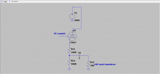
Hi everyone. As the last stage of a preamp I would like to use a DC coupled cathode follower.
Can I calculate the peak output curent swing using this formula:
Ipk= B+/(rp+ Rload) ?
If so, for my "design" ( schematic below) this would mean
0.0046A = 300/( 62500+476)
0.0046A into 476Ohm = 2.26V Peak. Does this mean I can input 2.26V peak to the cathode follower before it clips?
I hope I understand well that Rload in my case would be 500 || 10000
Attachments
This might help:
The Valve Wizard -Cathode Follower
The way you have the cathode follower drawn, R12 is the cathode load resistor. But 500R is far too small a value for that. It should be 100k. R11 can be 100R or thereabouts, used as a build-out resistor. You can leave that out, though. So basically short out R11 and make R12 100k ohms, at least for a start.
--
That is not "a cathode follower output" any more because you are not straight taking output signal from cathode but from a 200:1 resistive attenuator, which completely separates it from following stage (a power amp) and the Math you are trying to apply becomes sort of irrelevant.
From the point of view of the next stage input impedance (10k) , source impedance is now 500 ohms, completely unrelated to cathode follower output impedance, and separated from it by a 100k resistor.
Peak signal level is now 1/200th of real cathode signal swing, now you will have at most some 1.25Vpp so some 400mV RMS are available, best case.
Idle current through that 500 ohm resistor is between 1mA and 1.5mA , simply because it´s in series with tube and 100k resistor, so that also defines maximum current possible into the load.
In a nutshell, although you show a cathode follower, the signal voltage and current available at the real output point are quite different and very far from it ..... because output connector is electrically very far from the actual cathode.
I can follow your reasoning there, but the thing is, valve "constants" like rp really aren't constant! The "rp" we see on the datasheet is an approximate value that applies to a certain relatively small region of the graph, but it doesn't really apply to DC operating conditions, or to other regions of the graph.Can I calculate the peak output curent swing using this formula:
Ipk= B+/(rp+ Rload) ?
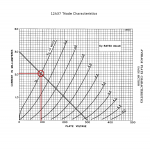
So one way to get an answer is to plot a load like on top of the triode characteristic curves. In the attached image, I've done this for a 300V B+ and 100k load.
The interesting thing to note is that the 12AX7 needs nearly 100 volts across itself, between anode and cathode, even when biased "fully on", i.e. Vgk = 0 volts. So only about 200 volts can be applied to the 100k load. The 100k resistor, of course, follows Ohm's law, so 200 volts across it causes 2 mA of current to flow through it. Adding on the little 500 ohm resistor makes negligible difference to these values (500 ohms is half of one percent of 100k). So that means you circuit can deliver 2 mA, maximum, into your 500 ohm resistor.
If we cut the valve off, that current drops to 0 mA. So the maximum peak-to-peak current swing through the 500 ohm resistor is 2 mA. Ohm's law now gives us the peak-to-peak voltage across the same 500 ohm resistor: Vpp = 2 mA x 500 ohms = 1 volt peak-to-peak.
There you go, then. You have a maximum of 350 mV RMS (same as 1 Vpp) available across the 500 ohm resistor. If you were to short the 500 ohm resistor (feed the signal into a device that had zero input impedance), you would get a maximum signal current of 2 mA peak-to-peak, or 0.707 mA RMS.
You didn't ask, but just in case: 350 mV rms is a rather hot "instrument level" signal that should work with most guitar FX pedals. However it is probably a bit too small to work well with a "line level" input on a mixer, P.A. system, etc, if that is what you had in mind. I usually assume a nominal 100 mV RMS for instrument level, and 1 V RMS for line-level.
Of course you can always tweak that 500 ohm value to provide the signal level that works best with the equipment you plan to use.
-Gnobuddy
Attachments
...0.0046A = 300/( 62500+476)...
Where is the 100K??
The 62K on the sheet is not full-on, as Gnobuddy shows we may take 50K. 50K+100K is 150K. 300V/150K is 2mA. This is the most we could push toward the 500r; we really get a hair less, 1.99mA.
This actually splits between the 500r internal and the 10K actual useful load. 0.099mA max to real load.
What can you input? Figuring 50K tube and 100K load, you can swing up to about 2/3rd of 300V, like 200V. In principle you can swing down to zero, but distortion gets huge if current swings more than 2:1 or 4:1; you can swing grid and cathode down to 50V, so 150Vpp 50Vrms at grid. Of this only 1/200th gets to the external load, 0.25Vrms.
Very good stuff, a lot of food for the brain that I need to digest.
I appreciate the time you all took to help me with this. Your posts will be reread a lot by me untill something hopefully clicks at a certain time.
What I am trying to accomplish with this circuit is this:
Make a 300V peak to peak signal level into line level and buffer it.
The stage before the "buffer' ( can't call it CF, I learned JMFahey), is clipping.
Would it be better to add a CF after this buffer to give it a lower input to work with?
I am happy with the sound of the overdriven stage+ dc coupled buffer, will the sound change if I let it feed a 10K input as is?
In my opinion, there is nothing wrong with the circuit as you have shown it. It reduces a dangerously large signal to a safe level, and lowers output impedance to about 500 ohms, which is more than low enough....trying to accomplish...Make a 300V peak to peak signal level into line level and buffer it.
From the examples of bad FX loop design in Merlin Blencowe's guitar preamp book, I would say you have done a much better job than a number of commercial guitar amp designers.
You might find you need to tweak the 500 ohm resistor value up or down a bit to get the right signal level for your external equipment. This won't affect the circuit analysis as long as this resistor remains much, much smaller than the 100k resistor in series with it.
Nothing wrong with it, truly. Just build it and enjoy it.
")
-Gnobuddy
Feel free to ask questions until something does click. Answers are free here, you know.Your posts will be reread a lot by me until something hopefully clicks...
-Gnobuddy
Feel free to ask questions until something does click. Answers are free here, you know.
-Gnobuddy
I almost feel guilty at times, picking you's guys brains. Then again, no one is forcing anyone to answer our newbie questions.
The schematic above is based on an SLO100 (attached below). Soldano recommends a 1k || with the stock 2.2k (R24)... which works out to ~688R. I've built an SLO pre and a 680R works perfect (assuming you want a more pedal friendly signal).
Attachments
If our ancestors had hoarded their knowledge, our species would probably have died out. "I figured out an easy way to kill a wooly mammoth, so I have lots of food, but I won't tell anyone else how I did it, so the rest of my tribe will starve to death, ha ha!"I almost feel guilty at times, picking you's guys brains. Then again, no one is forcing anyone to answer our newbie questions.
So evolution wired our brains to share knowledge, and to enjoy doing that. If we weren't wired like that, we wouldn't be here.
Well, most of us. Evolution has no ethical preferences, whatever strategy lets you survive long enough to reproduce will let your genes continue. So some greedy hoarders also survived, because they got enough food for themselves, even though the rest of their tribe starved to death.
These days, their descendants do very well in our more capitalistic societies. Some of us even hold up those greedy hoarders as examples for our children to follow.
Back on topic, yikes, Michael Soldano certainly loved sprinkling extra triodes everywhere!
-Gnobuddy
There will be much more questions Gnobuddy, a lot of things still need to click here. Learning this stuff,to me, feels similar to practicing guitar: sometimes there is little progress for quite some time and then suddenly you have small breakthroughs that in the end all add up and cross pollinate.
The beauty of evolution should be that it is self correcting. There wil be interesting ethical questions raised when humanity gets good at this DNA manipulation thingy. Its beautifull that people share their knowledge here, it must indeed attract the more altruistical people, although not every forum is as pleasant as this one.
The beauty of evolution should be that it is self correcting. There wil be interesting ethical questions raised when humanity gets good at this DNA manipulation thingy. Its beautifull that people share their knowledge here, it must indeed attract the more altruistical people, although not every forum is as pleasant as this one.
I know that feeling well. I was stuck for a decade at one point, while going through college and having no spare time, money, or energy. Eventually I finally plucked up my courage and went looking for a good guitar teacher to get me unstuck.Learning this stuff,to me, feels similar to practicing guitar: sometimes there is little progress for quite some time and then suddenly you have small breakthroughs that in the end all add up and cross pollinate.
At the same music studio, I later saw a "$5 for 5 drum lessons" flyer. I signed up, and was surprised some weeks later to find I was starting to use the thicker strings on my guitar as the bass drum, and the thinner strings as the snare drum, so my rhythm guitar patterns were starting to borrow a little of the sound and feel of drumming.
After that I tried putting occasional drum fills into my rhythm guitar playing, for instance, after a silent pause in the song.
More recently, when I began trying to sing harmonies, sure enough, that started to influence my guitar solos, and little bits of harmony and countermelody would show up in my solos.
Music is such a fascinating thing. There is no end to how far you can go, how much you can improve, how many new things you can learn!
There are major mistakes that have not been corrected in hundreds of millions of years, though. For instance, having our food-pipe share an opening with our breathing-pipe: a disastrous recipe that has led to millions of deaths by choking during the history of amphibian, reptilian and mammalian life on land. Insects don't have the same evolutionary mistake, as far as I know.The beauty of evolution should be that it is self correcting.
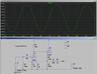
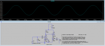
Back on topic, I'm attaching a screenshot of an LTSpice simulation of the Soldano common-cathode stage/ DC coupled cathode follower / FX send circuit we've been discussing.
In the simulation, I turned up the input signal until the CF was just starting to clip. The FX send waveform is shown in the graph, and sure enough, reaches to pretty much +/- 500 mV, i.e. it is 1 volt peak-to-peak, almost exactly matching our quick estimate based on drawing a 100k load-line.
Of course an LTSpice simulation like this is only as good as the mathematical model of the 12AX7 we're using. But it is nice to see the simulation in pretty good agreement with the back-of-the-envelope calculation.
-Gnobuddy
Attachments
I also did a LT Spice simulation using your values, but got a different result. Looking at your sine wave input I see 1.5V. Output is slightly clipped. I had to input 2.25V to get a similar result. Also there is more output swing in my simulation, around 1.4V peak to peak.
Do I need to add the V3 from your schematic to do a proper transient sim?
I have added my spice outcome below.
Do I need to add the V3 from your schematic to do a proper transient sim?
I have added my spice outcome below.
Attachments
I think the only difference is that we happen to be using two different mathematical models of the half-12AX7 triode. Honestly, I don't know which one is closer to reality.I also did a LT Spice simulation using your values, but got a different result.
A couple of things: one, the difference between 1 Vpp and 1.4 Vpp is only about 3 dB, which is barely noticeable by the human ear. Two, real 12AX7s vary as well, and its quite likely that a real one may exactly match the datasheet.
So, though the difference between your sim and mine is annoying, both results are in the ballpark. At least we know that we didn't make some sort of huge howling blunder in our back-of-the-envelope estimations.
With tube simulations, this seems to be about the best we can hope for. (Fairly accurate models for semiconductor devices are much easier to find.)
V3 was there for something else. One way to find the output impedance of a circuit in LTSpice is to feed an AC voltage into the output, and then measure the amount of current that flows back into the circuit. Dividing (peak) voltage by (peak) current then gives you the output impedance.Do I need to add the V3 from your schematic to do a proper transient sim?
That's why I had V3 and R6 in my schematic.
(The unsurprising result, by the way, was 500 ohms, as nearly as I could tell from the graph. Just as we figured in our back-of-the envelope calculation earlier.)
-Gnobuddy
Ow yeah I use a similar trick to measure output impedance. I inject a current source with an ac amplitude of 1 to a node of interest. Then you can add an V/I expression on the plot.
I am interested in finding the limit of the load a 12ax7 can drive. Opamps usually want a load not heavier then 2K. Is there such a limit for a 12ax7?
I am interested in finding the limit of the load a 12ax7 can drive. Opamps usually want a load not heavier then 2K. Is there such a limit for a 12ax7?
Many op-amps are current-limited; the figuring is different.
The popular TL071 opamp has internal resistors like 300 Ohms. It drives 2,000 Ohms fine.
The 12AX7 with the customary 100K plate resistor is an effective source like 40K Ohms. >100X higher than TL072.
Why do you need to make a 12AX7 work hard? TL072 is 19 cents.
The popular TL071 opamp has internal resistors like 300 Ohms. It drives 2,000 Ohms fine.
The 12AX7 with the customary 100K plate resistor is an effective source like 40K Ohms. >100X higher than TL072.
Why do you need to make a 12AX7 work hard? TL072 is 19 cents.
And they are wonderful things, no longer appreciated as the miracle of technology that they are. It took about 250,000 years for homo sapiens sapiens to go from hunter-gatherer in the African savannah to the first op amp.TL072 is 19 cents.
The typical op amp has 30 V between supply rails, the typical 12AX7 stage has 300 V. The op amp happily supplies 10 mA, the half-12AX7 will manage 1 mA.
So the tube runs on ten times as much voltage, and delivers one-tenth the current. Impedance being voltage/current, we can make the ballpark estimation that the triode will only drive a load that's a hundred times stiffer than the op amp...two hundred kilo ohms instead of two kilo ohms.
That's not too far off base, though voltage gain is limited and precious when it comes to tubes, so we tend to use loads that are even higher impedance than that. Which is why you see 500k and 1 meg volume pots wired to 12AX7s.
It has crossed my mind that the early history of electricity was all about static electricity: very high voltage and very low current. Today's semiconductors go to the opposite extreme, with the CPU for your computer drawing tens of amperes at maybe 1.3 volts. And the century-old vacuum tube technology fits neatly in the middle, right between static electricity and what is sometimes loosely called current electricity.
Incidentally, if you want a half-12AX7 to deliver lots more drive, the solution is simple: wire a suitable high-voltage, N-channel MOSFET to the triode in source-follower mode. The MOSFET will be audibly transparent, but work as a very effective buffer.
-Gnobuddy
Last edited:
I seriously thought about adding an opamp or a mosfet to act as an extra buffer, but wanted to see how far I would get by using what is already there in the design.
What I do know from playing with opamps and a too heavy load is that they usually do work, but they start to behave funky ( clipping in my case). I thought that maybe a tube had a similar behaviour.
I have another question ( they keep on coming!)
So on this 12ax7 buffer circuit I drew ..is it true that since there is no plate resistor there will also be no ac voltage at the plate? I am feeding it ac at the grid. In my simulation I see no ac voltage at the plate.
- Status
- This old topic is closed. If you want to reopen this topic, contact a moderator using the "Report Post" button.
- Home
- Live Sound
- Instruments and Amps
- Calculating how much V and I a CF can deliver