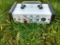
The TrAmp – my smallest guitar amp
Over the years I designed a lot of guitar amps for my private application. So I never had to care about any marketing aspects – it is my own taste that counts here, and I am free to choose the best of all solutions available. For a lifetime I played DIY-amps and do all my designs from scratch. That includes designing the circuit diagrams, pcb-layouts, source the parts, populating pcb layouts, mounting things into an enclosure etc. The latest design is the smallest one – a battery driven amp connected with a ZT-lunchbox.
I call it the trAmp
My goals were
- as simple as possible
- fitted with the basic features, but not more
- lightweight
- energy saving for long battery standing time
- self-explanatory
- off-the shelf components, no exotics
- lowest noise, highest dynamic range
Consequently this is a pure solid-state solution, most of it analogue circuitry.
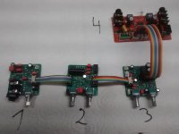
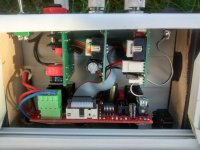
The result are 4 PCB-Modules that can be seen on the fotograph – an overview:
1. 2-channel Pre-Amplifier
Channel 1 with variable distortion potentiometer, ranging from total clean to medium distortion. A compensating circuitry keeps loudness constant over the full range so there is no need for an additional vol potentiomer to adjust loudness at different distortion levels.
With a switch or footswitch the 2nd channel can be selected. This one provides a fixed high gain distiortion. I call this the „hot“ channel or the „Gary Moore“ (R.I.P.) channel.
2. Fx Board
This acts either as a Reverb or Chorus utilizing Spin-Semi chip FV-1. With the chorus potentiometer set at minimum the reverb is active. The reverb potentiometer slides between totally dry and totally wet signal thus allowing extreme reverb effect as well.
Turning the chorus potentiometer clockwise switches to chorus and varies rotational speed of chorus. There are 2 LEDs indicating the current active potentiometer.
3. Master Board
Here you find master volume and sound potentiometer. This sound control combines a treble cut-boost control with a bass boost-cut control giving a wide sound variation with a single knob.
A 3.5mm jack can be connected as a line in for some external music from mobile phones etc. Otherwise this can be used as line out to connect to a PA-system.
To avoid harsh clipping of the power stage there is a soft clipping circuitry on board. This automagically adapts to actual supply voltage giving the maximum of soft clipped output power under all conditions.
4. Power Board
For a battery driven system the TPA3116/3118 from TI is hard to beat. It is happy with a single supply upto 24V=, does not require a heat sink, has a low standby-power consumption and is imho foolproof (over the years I did not encounter a single fail). The TPA3118 used here is set as mono amp in PBTL configuration giving the lowest possible losses. Gain is set to minimum for lowest hiss. Both inputs are driven symmetrically for best noise and sound performance.
Besides the class-d-amp a microcontroller (Attiny25) is implemented to control powermanagement. This includes a low-battery warning (LED blinking) at low battery voltage followed at the end by a forced low-battery shutdown to protect the Li-Ion accus from deep discharge. Additionally there is a deadman-function, i.e. after 15Min without any audio input the system shuts down. This prooved very useful for the elderly (like me).
Over the years I designed a lot of guitar amps for my private application. So I never had to care about any marketing aspects – it is my own taste that counts here, and I am free to choose the best of all solutions available. For a lifetime I played DIY-amps and do all my designs from scratch. That includes designing the circuit diagrams, pcb-layouts, source the parts, populating pcb layouts, mounting things into an enclosure etc. The latest design is the smallest one – a battery driven amp connected with a ZT-lunchbox.
I call it the trAmp
My goals were
- as simple as possible
- fitted with the basic features, but not more
- lightweight
- energy saving for long battery standing time
- self-explanatory
- off-the shelf components, no exotics
- lowest noise, highest dynamic range
Consequently this is a pure solid-state solution, most of it analogue circuitry.
The result are 4 PCB-Modules that can be seen on the fotograph – an overview:
1. 2-channel Pre-Amplifier
Channel 1 with variable distortion potentiometer, ranging from total clean to medium distortion. A compensating circuitry keeps loudness constant over the full range so there is no need for an additional vol potentiomer to adjust loudness at different distortion levels.
With a switch or footswitch the 2nd channel can be selected. This one provides a fixed high gain distiortion. I call this the „hot“ channel or the „Gary Moore“ (R.I.P.) channel.
2. Fx Board
This acts either as a Reverb or Chorus utilizing Spin-Semi chip FV-1. With the chorus potentiometer set at minimum the reverb is active. The reverb potentiometer slides between totally dry and totally wet signal thus allowing extreme reverb effect as well.
Turning the chorus potentiometer clockwise switches to chorus and varies rotational speed of chorus. There are 2 LEDs indicating the current active potentiometer.
3. Master Board
Here you find master volume and sound potentiometer. This sound control combines a treble cut-boost control with a bass boost-cut control giving a wide sound variation with a single knob.
A 3.5mm jack can be connected as a line in for some external music from mobile phones etc. Otherwise this can be used as line out to connect to a PA-system.
To avoid harsh clipping of the power stage there is a soft clipping circuitry on board. This automagically adapts to actual supply voltage giving the maximum of soft clipped output power under all conditions.
4. Power Board
For a battery driven system the TPA3116/3118 from TI is hard to beat. It is happy with a single supply upto 24V=, does not require a heat sink, has a low standby-power consumption and is imho foolproof (over the years I did not encounter a single fail). The TPA3118 used here is set as mono amp in PBTL configuration giving the lowest possible losses. Gain is set to minimum for lowest hiss. Both inputs are driven symmetrically for best noise and sound performance.
Besides the class-d-amp a microcontroller (Attiny25) is implemented to control powermanagement. This includes a low-battery warning (LED blinking) at low battery voltage followed at the end by a forced low-battery shutdown to protect the Li-Ion accus from deep discharge. Additionally there is a deadman-function, i.e. after 15Min without any audio input the system shuts down. This prooved very useful for the elderly (like me).
Attachments
Last edited:
More pictures...
Attachments
-
 02a_top_inside_IMG_20181011_112133170.jpg221.7 KB · Views: 506
 -
 05_tramp_rear_IMG_20181011_112254942_HDR.jpg199.9 KB · Views: 226
 -
 04_tramp_front_IMG_20181011_112309096_HDR.jpg300.6 KB · Views: 463
 -
 03_top_lawn_IMG_20181011_112119966_HDR.jpg285.9 KB · Views: 472
 -
 02b_top_inside_IMG_20181011_112143862_HDR.jpg177.2 KB · Views: 496
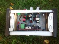
Enclosure
This top is based on a piece of rectangle cable pipe with wooden plates at both sides. Two strong magnets connect it with the lunchbox.
Labelling of Control Elements
The templates have been created with inkscape and printed with a black laser printer onto self-adhesive white label sheets.
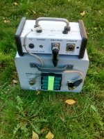
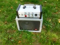
Rechargeable Batteries
Over the years I used S(ealed) L(ead) A(cid) batteries as these were unexpensive. But they are bulky and so I switched to 18650-Li-Ion-Cells. These are industrial standard found in any notebook-akkus, cordless-tools etc. With 4 cells wired in series an operating voltage between 14~16V is available. To avoid any headaches with charge balancing problems and achieve max lifetime I bought a 4-slot charger with 4 separate controlled charging slots and displays monitoring the status of each slot. So I recharged the cells that were to weak for my cordless drill and recycled them for this guitar amp, giving lots of acoustical power!
The Loudspeaker
Although I used the ZT-Lunchbox (i.e. the passive version w/o amp) I replaced the speaker with a Jensen MOD-15 (4 Ohms version). It fits exactly into the holes and pleases me more than the original.
This top is based on a piece of rectangle cable pipe with wooden plates at both sides. Two strong magnets connect it with the lunchbox.
Labelling of Control Elements
The templates have been created with inkscape and printed with a black laser printer onto self-adhesive white label sheets.
Rechargeable Batteries
Over the years I used S(ealed) L(ead) A(cid) batteries as these were unexpensive. But they are bulky and so I switched to 18650-Li-Ion-Cells. These are industrial standard found in any notebook-akkus, cordless-tools etc. With 4 cells wired in series an operating voltage between 14~16V is available. To avoid any headaches with charge balancing problems and achieve max lifetime I bought a 4-slot charger with 4 separate controlled charging slots and displays monitoring the status of each slot. So I recharged the cells that were to weak for my cordless drill and recycled them for this guitar amp, giving lots of acoustical power!
The Loudspeaker
Although I used the ZT-Lunchbox (i.e. the passive version w/o amp) I replaced the speaker with a Jensen MOD-15 (4 Ohms version). It fits exactly into the holes and pleases me more than the original.
2-Channel Pre-Amp Module
Guitar-input is amplified by a gain of 3V/V by U2A. Input impedance is given by R3=1M0. The CMOS input of OPA1678 provides en=4.5nV/root(Hz) at very low input current noise. In fact there was no difference in noise figure with a preceeding SK170 source follower. So I dropped this stage. Omitting the JFET input stage improved power supply rejection significantly. The reason was obviously the non-ideal current source behaviour of the JFET.
Channel 1
The upper part of the circuitry is channel 1, basically an active Si-diode clipping circuit. The first segment of the stereo gain pot controls overdrive gain, i.e. distortion. The second segment of the gain pot reduces post amplifier gain with increasing distortion thus yielding constant loudness over the entire distortion range. The curve is adjusted by selecting the parallell resistor R10.
Pre- and De-Emphasis
To prevent the low notes of a distorted chord from drowning out the higher ones, a bass cut R4,C3 is inserted between input amp and distortion stage. As this would give a flat sound specially at low distortion rates, a complimentary bass boost R14,C7 is added after the distortion stage for overall compensation. The crossover frequency is set to RC=330us corresponding to about 500Hz. Certainly this contributes to a special sound signature.
Channel 2
This is a simplified version of channel 1 with very high gain, exceeding the gain of channel1 even in the max position of the pot.
Analogue Switching
Two anti-seriell wired off-the-shelf CMOS transistors act as bidirectional switch. The gate circuitry slows down switching transients to minimize any pop sounds.
Choosing alternative OP-Amps
OPA1678 is the best in class I actually found for this purpose. But the choice of op-amps is not really critical. CMOS-/JFET-inputs are preferrable for high impedance guitar outputs but are not mandatory if a bit more noise is acceptable. Even TL072 will do a good job.
Attachments
Last edited:
Thank you for the kind words.
The next step will be a look at the FX-board with reverb/chorus. Its core is spinsemi FV-1, a well known effects chip created by Keith Barr (R.I.P), the genius behind Electro Harmonix, Alesis and others. Based on the datasheet applications, I added a 3.3V stepdown converter and an automatism that switches between chorus and reverb, depending on the setting of the chorus potentiometer. This requires swtching both the effect selection bits as well as re-routing the analog signal path. In chorus mode both outputs of the FV-1 are routed to the output without any dry signal in it. In reverb mode you can slide between 100% dry and 100% wet signal.
All in all there is only one of both effects at a time as there is only one FV-1 on board.
Analog inputs and outputs levels of FV-1 are limited to <3Vpp thus I choose max level of 1Vrms=2.8Vpp for input and output.
This level is close to the max peak a guitar pickup may deliver when stroken very firmly. For that reason the pre-amp exhibits an overall gain close to unity in absolute clean position.
This appears to be quite little pre-amp gain, but I prefer my effect loop not to clip under all conditions, without a dedicated limiter.
Although the FV-1 incorporates two independent audio channels it is wired here as mono in a mono system.
To minimize current consumption the OP-amps are supplied by 3.3V rails. There are not so much low-noise low-power OP-amps with rail-to-rail inputs and outputs suitable for that low voltage on the market. TS922 from ST was my preferred choice.
Attachments
Last edited:
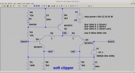
Soft Clipping
It was in the seventies of last century that I discovered the CA3080 in a RCA databook. There was a plot of the transfer curve and I knew instantly: This perfect s-curve is the one I was looking for to build the a fuzz box with a smooth transition from clean to distorted sounds. From that day on this was my standard part for many distortion modules.
When, after a long pause, I re-entered the analogue audio world, these chips were long gone. Although I have a small stock of NOS CA3080 I dislike the idea of designing in NOS parts so I had to look for another solution. Looking at its internal circuitry I decided to emulate it using some discrete parts. What remains is a bjt differential amplifier fed by a current source - no rocket science so far.
This circuitry is a perfect interface between the volume potentiometer and the analogue inputs of the class-d amp for several reasons:
-With emitter degeneration resistors close to zero the transition is the smoothest and at the same time voltage gain reaches its maximum.
-This comes in handy because a high gain behind the master volume potentiometer is a desirable feature in such a guitar amplifier.
-Output level increases linearly with supply voltage. Once set correctly the class-d output stage shows max possible soft limiting behavoiur over a range of supply voltage.
-On the other hand considering noise (hiss) a high master gain normally is a no-go. But as this discrete bjt amp stage exhibits very low noise voltage the overall noise is surprisingly low even at very low sound levels.
-the symmetric output is noise immune even with unshielded cable and fits perfectly to the symmetric input of class-d amp
The behaviour of the soft clipper can be studied using this simplified LTSpice simulation.
Attachments
Last edited:
module no 3 - the master section, including
preamp input
karaoke input for MP3 player, smartphone etc
1-knob equalizer. Basically the classic baxandall, but with bass pot reverted
master volume and softlimiter. All values are fitting to my TPA3118 power modules with min gain set.
symmetrical output for TPA3118 power module
optional bluetooth dongle
solo footswitch. A 6dB gain can be turned on for solo playing.
Attachments
Last edited:
- Status
- This old topic is closed. If you want to reopen this topic, contact a moderator using the "Report Post" button.
- Home
- Live Sound
- Instruments and Amps
- the trAmp - my latest and smallest guitar amp