Do you measure the current in (what is the value of) cathode resistor of V4 and V5, because I don't see any in schematic. The idle power dissipated is < 15W both tubes which is normal but then you get V4 red plate or over dissipated (more than 25W) when driven, looks like V4 is overloaded (because the power is not fully outputted, a mismatch somewhere in OT or tube), as shown in your photos I saw the output waveform is asymmetric and distorted. Or could be the other way V4 is working too hard. You can swap the tubes to see any difference.
Last edited:
first i would look at the bias supply and figure out why the voltage is low, i would expect to find between -50 to -60 volts there.(the schematic you provided shows a bias voltage of -57 volts) next i would lift the grid side of the phase inverter caps to check for DC leakage, even a small amount of leakage there would reduce the gain or cause imbalance. what are the component values for the the presence control, that's part of the negative feedback for the output stage and are often "modded" with bad consequences.
P.S. the other thing i would be concerned with is the insulation resistance of the wire used in this amp it looks "cheap" and with cable ties strapping it together it's possibly changing leakage values when "lifted"
also what's with the nasty looking ground buss strapped to the board that i see in the pictures.
Last edited:
Hello Koonw, we are here again. Yes, I can try to do what you suggest, but if the problem in effect is the board I've to insulate near anything that can have a Voltage greater than few volts to have a good result. In this case is not better to unsolder all and transfer to a new board? Probably is faster and the result could be better and more sure. What about bakelite I mentioned in my previous post?
I can't understand why your board is so conductive, please read this for some clues. If the board has been anti-static treated, there will some leakages. But I also think such coating is not permanent and can be removed or cleaned by some strong solvent (turpentine?).
News from Italy!

Only doing this, without any other change, what happens: the Bias current previously setted to 30mA goes to 62mA. Reducing again to 32mA (not possible going below bacause the trim was fully counterclockwise) the Bias voltage lift to -47Vdc. For information on the three free turrets in the picture I measured around 3Vdc.
In any case red plating is reduced (not disappeared) and V4 more than V5 (also swapping the tubes).
As further information I take a picture from the scope connected to speaker output, with a signal of 100mV, 400Hz, sinusoidal applied to High Input, gain (pre) on 12 and master volume fully clockwise.
 .
.
First of all I try to lift in-air the part after the PI coupling caps, with the 2 RG resistor and the node with brown cable coming from the Bias trim(see the picture below)first i would look at the bias supply and figure out why the voltage is low, i would expect to find between -50 to -60 volts there.(the schematic you provided shows a bias voltage of -57 volts)
Only doing this, without any other change, what happens: the Bias current previously setted to 30mA goes to 62mA. Reducing again to 32mA (not possible going below bacause the trim was fully counterclockwise) the Bias voltage lift to -47Vdc. For information on the three free turrets in the picture I measured around 3Vdc.
In any case red plating is reduced (not disappeared) and V4 more than V5 (also swapping the tubes).
As a premise both the caps were replaced when I start to work on this amp. In effect I measured 1.5Vdc on the cap going to V5 and -2Vdc (????) on V4 one.next i would lift the grid side of the phase inverter caps to check for DC leakage, even a small amount of leakage there would reduce the gain or cause imbalance
I checked again the components and the respect of the schematic. It seems all right.what are the component values for the the presence control, that's part of the negative feedback for the output stage and are often "modded" with bad consequences
As further information I take a picture from the scope connected to speaker output, with a signal of 100mV, 400Hz, sinusoidal applied to High Input, gain (pre) on 12 and master volume fully clockwise.
.well that's still all rather suspect... as i don't know your measurement technique/process can i ask if the measurements are all taken with respect to ground? as in not simply across a component?
the bias is still to low if there's residual red plating.
even new caps can be leaky so that should not be dismissed yet.
turn things down the levels are way high for even test purposes and that scope trace shows some ringing so yes capacitor troubles (random re-capping can create more problems sometimes)
Yes, all the measurments are taken with respect to ground.well that's still all rather suspect...
as i don't know your measurement technique/process can i ask if the measurements are all taken with respect to ground? as in not simply across a component?
Yes, but is quite improved when I lift in-air the RG resistor. As when I worked on the pre side and find that the board is conductive lifting in-air all the HV nodes. It seems that the board conduct a +Vdc voltage of a value depending from the zone. This explain why lifting in air the RG resistors the voltage moved from -41Vdc to -47Vdc. I'm quite sure that if I lift also all the Bias part, including the trim and connected resistors I'll arrive to the Voltage you see in the schematic.the bias is still to low if there's residual red plating.
May be there're also other problems, but with this situation (the conductive board) that alter all the values the troubleshooting is really complicated and some readings may be misleading. Other suggestion?
If no tomorrow I'm in Milan and visit a shop to find a new board. Have you suggestion for other material/components to be replaced if I go to unsolder all and transfer to the new board?
I agreed you can use insulated turret at all costs and problem solved, but just let deal with the real cause behind this. Here are some of links more relevant and similar to this OP problems:-
In some case only a Megger (500V & above) can measure the insulation resistance correctly, an ordinary DMM can not (always 0). What is Megger Test and How is it Performed | Carelabz.com
Circuit board insulation and high voltage Circuit board insulation and high voltage | Electronics Forums
Anti-static treated board Hoffman Turret Board with Black G10
Crap board YouTube
Last edited:
maybe i'm not understanding because of language conventions or mistakes in translation. would "free" actually be "three" in the number of turrets?
as many amps as i've worked on i've never encountered this sort of thing before so if the board is truly conductive then leakage to ground would be messing with more then just the output stage,is it?
as many amps as i've worked on i've never encountered this sort of thing before so if the board is truly conductive then leakage to ground would be messing with more then just the output stage,is it?
Ya, this is DIY Marshal kit I think, we don't know the quality of the parts. As OP shown, it's all over the places (maybe you should read some more in the posts of this thread for better understanding). The lift of components in air has relieved most problems with pre-amp (front-end) at least DC wise, but the signal esp. the high swing signal yet to be ascertained. The bias of output stage is affected, but it may have other problems beside the board in question.
i did read through the posts which is why i suggested that some other form of circuit trouble was at play because i've only ever seen that sort of thing after a board has carbon arcing from massive component failures and carbon contamination that high heat bonds to all surfaces.
if the OP'sters board is in fact behaving like the one in the link you provided in post#50 -CRAP BOARD then yes change it, as for me i've learned something new here, i still think there's more to it but i've been wrong before.
if the OP'sters board is in fact behaving like the one in the link you provided in post#50 -CRAP BOARD then yes change it, as for me i've learned something new here, i still think there's more to it but i've been wrong before.
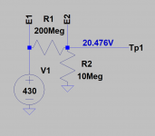
I did a Megger (ZC-70) test of blank eyelet board, the insulation between 2 eyelets is about 200 Meg. The HT is 430V and with DMM of 10Meg, I measure about 20V, which agreed with sim or calculated result.
Attachments
Last edited:
Hello everybody, and sorry if I was not present in the last few days.
I use part of this time to substitute the board, and at same time to make some improvements (twisting of 6.3 heaters, they wasn't - aligment with th e original Marshall JCM800 schematic bacause the first one I originally posted is not completely correct) and a few mods (resonance, switchable cold clipper, switchable bright cap) - in attachment you can see the new layout.
View attachment 709055
First test: I applied to the input the usual 400Hz, sine wave signal, and the images at output jack are the following:
1) with both preamp and master 12 o'clock

2) with preamp fully clockwise and master 12 o'clock

3) with both fully clockwise

I still have a little of red plating, similar on both power tubes and strange values at Bias circuit. The voltage at the node between RG resistor is -41Vdc and the bias current of both power tubes is around 14mA (14mVdc measured at the end of both 1 Ohm resistors).
Thanks for your comments.
Ivan
Hello Koonw. I just posted the first results after the replacement of the board. I haven't the possibility to make the Megger test on the old board, but you are interested and curious I can send you a piece of the old one.
Let me know.
Another question, sorry I forgotten before. How can I measure the real output power of the amp. I still have the impression that it isn't 50w.
I saw the picture of the new board is not visible. It's here:

I use part of this time to substitute the board, and at same time to make some improvements (twisting of 6.3 heaters, they wasn't - aligment with th e original Marshall JCM800 schematic bacause the first one I originally posted is not completely correct) and a few mods (resonance, switchable cold clipper, switchable bright cap) - in attachment you can see the new layout.
View attachment 709055
First test: I applied to the input the usual 400Hz, sine wave signal, and the images at output jack are the following:
1) with both preamp and master 12 o'clock
2) with preamp fully clockwise and master 12 o'clock
3) with both fully clockwise
I still have a little of red plating, similar on both power tubes and strange values at Bias circuit. The voltage at the node between RG resistor is -41Vdc and the bias current of both power tubes is around 14mA (14mVdc measured at the end of both 1 Ohm resistors).
Thanks for your comments.
Ivan
I did a Megger (ZC-70) test of blank eyelet board, the insulation between 2 eyelets is about 200 Meg. The HT is 430V and with DMM of 10Meg, I measure about 20V, which agreed with sim or calculated result.
Hello Koonw. I just posted the first results after the replacement of the board. I haven't the possibility to make the Megger test on the old board, but you are interested and curious I can send you a piece of the old one.
Let me know.
Another question, sorry I forgotten before. How can I measure the real output power of the amp. I still have the impression that it isn't 50w.
I saw the picture of the new board is not visible. It's here:
Now the amp is fully compliant with original Marshall specs. I introduced some mods but all of them are switchable and excluded at this moment.
View attachment JCM800 2204 Schematic - 1988 (Marshall).pdf
In your opinion is not strange the very low bias current (14mA) with -41Vdc voltage at RG resisotr node. In many forums they say that -40Vdc is the correct voltage at this point (it seems that in the Mark Huss schematic this voltage is too high)
if the voltage is low you'll have clipping on the negative half of the wave form and red plating, too much and you clip the top half the waveform and it will sound brittle and weak the bias level needs to establish a "center" point for current to swing in both directions equally (let's remember that the grid bias voltage is negative, it needs to be in opposition to grid voltage to stop the tube from conducting too hard)
what is your plate voltage on the output tubes?
what is your plate voltage on the output tubes?
Last edited:
455Vdc at this moment. It's not perfectly stable, moving up&down around 1Vdc (I don't know if this is an issue).
===
In detail the mods are:
1) A switch to exclude the bright cap (now included)
2) A switch to change the 10K cathode resistor on V1a (cold clipper). The switch allow to change the value to 35K, 10k (actual value) and 5K.
3) Resonance. There is a 470k potentiometer in series to a 33k resistor in place of the standard 100k resistor (now the series is setted to 100k) and a cap in parallel (now exluded)
No need to send to me the old board as you have reveal enough details. I like your new board, I see got extra holes drilled on them. Your old board, like mine maybe FR2, which has less insulation resistance than FR4, but better heat resistance.
About -41V bias, you get about 14mA, this could be due to low screen grid supply voltage, maybe only 400V instead 450V. If SG2 is also 450V, you will get about 45mA. With lower current you get more cross over distortion, so something to check on.
About -41V bias, you get about 14mA, this could be due to low screen grid supply voltage, maybe only 400V instead 450V. If SG2 is also 450V, you will get about 45mA. With lower current you get more cross over distortion, so something to check on.
Last edited:
- Status
- This old topic is closed. If you want to reopen this topic, contact a moderator using the "Report Post" button.
- Home
- Live Sound
- Instruments and Amps
- JCM800 2204 Phase Inverter issue and other