Hi there
I have a cute little Supro Super 1606 valve combo from the late 1950s.
It sounds absolutely superb for the first fifteen minutes or so and then slowly starts fading in volume and sound quality, becoming ever more distorted as it gets quieter.
I've tried swapping out all the valves but with the same result.
Any ideas?
Any help or guidance gratefully accepted!
I feel that I need to make clear that I am not an electronics engineer and so don't know my way around a schematic/circuit diagram.
However, I have managed (with the use of graphic instructions - photos & component lists) to perform quite detailed modifications on valve amps and built countless effect pedal kits.
Some tech details
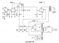
The 5-watt Super 1606 has a 5Y3, 6V6, and 12AX7 tube configuration, Magnetic Components transformers, and a 6x9" Rola speaker.
One volume control, no tone control.
Hi & Lo inputs.
I've attached a jpg of a schematic which I believe to be correct - though it mentions an 8" speaker whereas mine is the 6x9" version
I have a cute little Supro Super 1606 valve combo from the late 1950s.
It sounds absolutely superb for the first fifteen minutes or so and then slowly starts fading in volume and sound quality, becoming ever more distorted as it gets quieter.
I've tried swapping out all the valves but with the same result.
Any ideas?
Any help or guidance gratefully accepted!
I feel that I need to make clear that I am not an electronics engineer and so don't know my way around a schematic/circuit diagram.
However, I have managed (with the use of graphic instructions - photos & component lists) to perform quite detailed modifications on valve amps and built countless effect pedal kits.
Some tech details
The 5-watt Super 1606 has a 5Y3, 6V6, and 12AX7 tube configuration, Magnetic Components transformers, and a 6x9" Rola speaker.
One volume control, no tone control.
Hi & Lo inputs.
I've attached a jpg of a schematic which I believe to be correct - though it mentions an 8" speaker whereas mine is the 6x9" version
Attachments
All I would do is measure voltages around the valves, with care and record them when working fine and compare them when faulty.
Pay attention to the anode load resistors, on pins 1 and 6 of the 12AX7 and the cathode resistor voltage pin 8 of the 6V6.
Hi Jon
Kind thanks for your advice.
However I'm a trifle nervous about poking around inside a valve amp while it's fired up!
I do have a multimeter. And with a little more guidance I could probably complete the tests. Though I'm not sure about where to find the particular pins you mention or what setting I'd need to put my meter to test them.
Would I be correct in assuming that I'd attach the black cable from my meter to the chassis and then use one of the 'needle' probes to measure the pins?
And when you say 'pay attention to' do you mean be careful of them or are they the points to take readings from?
If so, would that be on the leg the other side of the resistor after the valve base connection, or at the actual valve base pin?
Sorry if these are really dumb questions, but as I mentioned in my original post, I'm not an electronic engineer and so don't have much in depth knowledge beyond being capable of swapping out old components for new...
Thanks for you patience!
Hi Jon
Thanks for your kind advice.
I have to admit that I'm a little nervous about poking around inside a fired up valve amp!
However, I'm sure, with a little guidance that it's not beyond the realms of my capabilities.
So, to clarify, when you say 'Pay attention to the anode load resistors...', I assume you mean these are the points where I need to take readings.
Having taken a look inside I'm a little lost as I can't see any resistors directly attached to any of the valve pins though they do lead to resistors elsewhere.
So I'm not sure where I need to take those measurements.
Also, would I be correct in thinking that I need to attach the black lead from the multimeter to the chassis before taking a reading with a needle probe attached to the other cable?
Final question - what do I set my meter to?
Apologies if these are all really dumb questions but as I mentioned in my initial post, I'm not an electronic engineer!
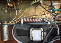
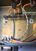
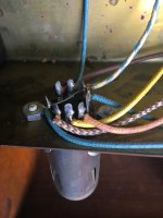
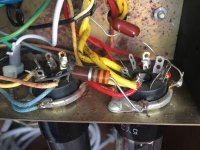
I've attached some photos taken from the inside of my amp.
Thanks for your kind advice.
I have to admit that I'm a little nervous about poking around inside a fired up valve amp!
However, I'm sure, with a little guidance that it's not beyond the realms of my capabilities.
So, to clarify, when you say 'Pay attention to the anode load resistors...', I assume you mean these are the points where I need to take readings.
Having taken a look inside I'm a little lost as I can't see any resistors directly attached to any of the valve pins though they do lead to resistors elsewhere.
So I'm not sure where I need to take those measurements.
Also, would I be correct in thinking that I need to attach the black lead from the multimeter to the chassis before taking a reading with a needle probe attached to the other cable?
Final question - what do I set my meter to?
Apologies if these are all really dumb questions but as I mentioned in my initial post, I'm not an electronic engineer!
I've attached some photos taken from the inside of my amp.
Anode resistors: unplug amp! remove tubes, discharge main filter cap (use an insulated 10k 5 watt resistor from 5y3 pin#2 to ground) check resistance across resistors on pins 1 and 6 on the 12ax7 should measure 100k and 270k.
INPORTANT: Filter cap may have 300+ volts across the terminals. use caution
If resistors check ok next step will be reflow solder joints and check coupling and bypass capacitors
INPORTANT: Filter cap may have 300+ volts across the terminals. use caution
If resistors check ok next step will be reflow solder joints and check coupling and bypass capacitors
Last edited:
Anode resistors: unplug amp! remove tubes, discharge main filter cap (use an insulated 10k 5 watt resistor from 5y3 pin#2 to ground) check resistance across resistors on pins 1 and 6 on the 12ax7 should measure 100k and 270k.
INPORTANT: Filter cap may have 300+ volts across the terminals. use caution
If resistors check ok next step will be reflow solder joints and check coupling and bypass capacitors
Aha!
A little knowledge is a dangerous thing etc etc...!
I do know that even unplugged electronic circuitry can still carry lethal voltages in the capacitors but I appreciate you mentioning it!
My spider sense is telling me you have some leaky caps that slowly allow unwanted DC through themselves as it warms up.
Oh really...?
How would I go about checking/fixing that?
Back in the early days, as an Electrician, we had a useful saying, "Keep one hand in your pocket". That will ensure that there is no route for the electricity to go through your body and kill you.
Almost true and a good idea if you are not familiar with the circuits.
USE CAUTION!
With a crocodile clip, connect the negative probe of your meter to the chassis, (negative ground). With one hand and your meter on the 500volt range or somewhere near it, check the voltages and make notes on pin2 of the 5Y3, pin 4 of the 6V6, pin 1 and pin 6 of the 12AX7. With your meter on 20volt range or near check pin 8 and pin 5 of the 6V6 then pin 8 of the 12AX7.
Repeat when the sound is faulty and any odd result will give you the clue you need.
For instance pin 5 of the 6V6 should be around zero, if rising above then replace the 0.05uF coupling capacitor.
Pin 2 of the 12AX7 is used in an unusual way; there is no cathode bias it uses negative grid bias instead and I have had high value carbon resistors drift. It may simply be that the 6M8 resistor is faulty.
Have fun and keep safe.
- Status
- This old topic is closed. If you want to reopen this topic, contact a moderator using the "Report Post" button.
- Home
- Live Sound
- Instruments and Amps
- Supro Valve Combo Diagnostic Help Required