Hi PRR!It does not need 40*50W= 2,000 Watts of resistors and two fans!
That photo was a bit of joke, but had the more serious intent of deterring punters from experimenting with the many inadequate circuits that can be found on the internet.
Since the OP is using a valve amplifier, resistor burnout is a serious consideration. An open circuit load resistor would leave the amp playing into an infinite load resistance, with the possibility of damaging the output valves.
Folks, this is an EL86 amp. "20W" may be optimistic.
George!!! PRR swore.
")
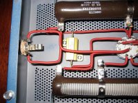
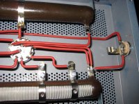
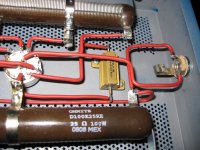
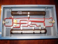
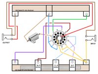
Try my "3 A.M" Simple Attenuator, lets you play full blast at 3 AM with the baby sleeping on the next room.
This one is for 30/40W amps, you can use a 25W main resistor ... or just use a 50W one and play it real safe.
Mount the main reistor on standoffs allowing air circulation around it and place it inside a perforated case for ventilation, it becomes quite hot.
The others ... no big deal.
You can build it "fixed" or use a rotary switch to change attenuation.
I´ve sold over 100 of them, very useful in the modern appartment life with "sensitive neighbours"
I really like this one
, and I am thinking of going with that design, amp will have 8 ohm outputs, but I would also like to experiment with 16 ohm attenuators, and also add some mods to it like coils and caps so it could sound more "natural" and I also found a vintage yougoslavian pot-switch which could also be used!Well, in any case it´s simple and inexpensive, so try it.
For testing you don´t even need a case or a board/terminals, just solder all 3 resistors together and place the 25/50W one on a brick or a couple stacked bathroom/kitchen tiles so as not to burn the table.
If you like it, then put it inside a suitable case.
For testing you don´t even need a case or a board/terminals, just solder all 3 resistors together and place the 25/50W one on a brick or a couple stacked bathroom/kitchen tiles so as not to burn the table.
If you like it, then put it inside a suitable case.
Good choice! And if you look closer at post #18 by JohnDH, you'll see that what he proposes is essentially the same attenuator JM Fahey suggested. The basic network is a "T" of three resistors that does three things at the same time: provides the right load impedance to the amplifier, provides the right amount of attenuation, and lastly, provides the right (high) source impedance to the guitar speaker.I really like this one
This last requirement is the one that is often forgotten - but look at the thread JohnDH linked. He made the measurements to prove that this is all that's required to make a really good attenuator that has only very slight effect on the EQ of the signal being fed to the speaker, which is what we want. No change in tone, only loss of SPL.
I think this is another one of those long-standing guitar related myths. The need for magic inductors, magic speaker drivers, et cetera, has made a lot of money for attenuator manufacturers, so I suppose it did benefit somebody. Just not the guitarist!...also add some mods to it like coils and caps so it could sound more "natural"
Again, look at some of the data JohnDH gathered. It shows the simple "T" attenuator with the proper resistor values doesn't change the EQ of the speaker signal enough to be, at most, barely audible.
However, our ears and brain do hear differently at low SPL, and that is not the fault of the attenuator. I assume you already know about the Fletcher-Munson equal loudness contours, now nearly 90 years old, but human hearing haven't changed at all in that time: Fletcher–Munson curves - Wikipedia
-Gnobuddy
Great idea--THANKS!! Total cost of components, including Switchcraft jacks and Orange Drop capacitor, is $142.57 plus shipping. Still cheaper than a THD Hot Plate (~$375) or a new one from DR. Z (~$390) . Expensive part is the 150Ω rheostat---it's $56.99!!eh, just build the Air Brake clone. Designed by the late Ken Fischer of Trainwreck amp fame. Now made by Dr. Z. I've built one, works great.
Last edited:
Good choice! And if you look closer at post #18 by JohnDH, you'll see that what he proposes is essentially the same attenuator JM Fahey suggested. The basic network is a "T" of three resistors that does three things at the same time: provides the right load impedance to the amplifier, provides the right amount of attenuation, and lastly, provides the right (high) source impedance to the guitar speaker.
This last requirement is the one that is often forgotten - but look at the thread JohnDH linked. He made the measurements to prove that this is all that's required to make a really good attenuator that has only very slight effect on the EQ of the signal being fed to the speaker, which is what we want. No change in tone, only loss of SPL.
I think this is another one of those long-standing guitar related myths. The need for magic inductors, magic speaker drivers, et cetera, has made a lot of money for attenuator manufacturers, so I suppose it did benefit somebody. Just not the guitarist!
Again, look at some of the data JohnDH gathered. It shows the simple "T" attenuator with the proper resistor values doesn't change the EQ of the speaker signal enough to be, at most, barely audible.
However, our ears and brain do hear differently at low SPL, and that is not the fault of the attenuator. I assume you already know about the Fletcher-Munson equal loudness contours, now nearly 90 years old, but human hearing haven't changed at all in that time: Fletcher–Munson curves - Wikipedia
-Gnobuddy
The added inductor and capacitor would give a boost to the low and the high which would compensate for the FM curves.
I dont find I need to try to build in for FM effects, so long as the sound is reasonably loud for its context, ie, loud enough for a jam, or loud enough for a room, or loud enough but not too loud for late at night. If its so quiet you cant hear it though, then better to play a different day.
In principle this could be done, but I don't think it's been done in practice. The few attenuator schematics I've seen usually obsess about (uselessly) reproducing guitar speaker voice coil inductance, rather than creating loudness compensation (FM curves).The added inductor and capacitor would give a boost to the low and the high which would compensate for the FM curves.
And if you did try to create proper loudness compensation with a passive (L/ R / C) network, it would be quite a challenge. The 60 dB SPL loudness compensation curve, for instance, requires nearly 20 dB of bass boost between 100 Hz and 1 KHz. To do that with a passive filter requires not only 20 dB of speaker attenuation at 1 KHz, but also some way to keep the input resistance of that filter reasonably constant at 8 ohms over the entire frequency range, in spite of the enormous bass boost.
I don't know if this is even possible without the filter / attenuator getting absurdly complex. At any rate, I have never seen a passive filter design that manages all three of these things - constant input impedance, constant output impedance, and Fletcher-Munson loudness compensation, all at the same time.
So I suggest a simpler and more effective solution - when you lower the volume with the attenuator, simply turn up the bass and treble on the amp to taste!
I can think of one more rather clumsy, but reasonably practical possibility: we could build a loudness compensation circuit into a guitar pedal, and use that in conjunction with the resistive speaker attenuator. But simply turning up the bass and treble on the guitar amp is so much simpler!
-Gnobuddy
I got the same shock recently. I wanted to use a 10 ohm, 12.5 watt rheostat for one of my projects, and was floored to find they were $60 at Mouser.Expensive part is the 150Ω rheostat---it's $56.99!!
Meantime, a 50 watt, 8 ohm, Lpad - which is actually two rheostats in one housing - costs $10.25 at Parts Express.
That price difference is enough to make me wonder if there's a way to modify an Lpad to make it into a plain-Jane rheostat.
-Gnobuddy
Expensive part is the 150Ω rheostat---it's $56.99!!
Yeah, that's the expensive part. You could still build it without the rheostat, but it won't be able to go really low, obviously. Just replace the rheostat with an 8 ohm 25w power resistor and wire it slightly different as shown in the diagram.
Attachments
In principle this could be done, but I don't think it's been done in practice. The few attenuator schematics I've seen usually obsess about (uselessly) reproducing guitar speaker voice coil inductance, rather than creating loudness compensation (FM curves).
And if you did try to create proper loudness compensation with a passive (L/ R / C) network, it would be quite a challenge. The 60 dB SPL loudness compensation curve, for instance, requires nearly 20 dB of bass boost between 100 Hz and 1 KHz. To do that with a passive filter requires not only 20 dB of speaker attenuation at 1 KHz, but also some way to keep the input resistance of that filter reasonably constant at 8 ohms over the entire frequency range, in spite of the enormous bass boost.
I don't know if this is even possible without the filter / attenuator getting absurdly complex. At any rate, I have never seen a passive filter design that manages all three of these things - constant input impedance, constant output impedance, and Fletcher-Munson loudness compensation, all at the same time.
So I suggest a simpler and more effective solution - when you lower the volume with the attenuator, simply turn up the bass and treble on the amp to taste!
I can think of one more rather clumsy, but reasonably practical possibility: we could build a loudness compensation circuit into a guitar pedal, and use that in conjunction with the resistive speaker attenuator. But simply turning up the bass and treble on the guitar amp is so much simpler!
-Gnobuddy
Not saying that the sound will be accurate the whole way through. Just that when turned down there is a loss in treble which some tweaked by adding a bypass capacitor and the resonance of the speaker is also simulated to an extent. Is it worth it? Not to me but you are taking two extremes, basic resistor network is ok but an added inductor and capacitor is inadequate for your standards. Some would say a presence control in an amplifier is a waste of one hole while another can't do without it. One size does not fit all, which sometimes is a good thing as we would all sound the same then.
Not what I was saying - we know the "T" network follows the Hippocratic oath, i.e., it "does no harm" to the frequency response. John DH has the measurements and sound clips to demonstrate that.you are taking two extremes, basic resistor network is ok but an added inductor and capacitor is inadequate for your standards.
But what happens with the added "bright" cap? Has anyone made the measurements to find out? Maybe it's wonderful, maybe it makes things worse than the simple resistive attenuator. I don't know, I haven't tested it myself, nor have I seen other people's published measurments.
As for emulating guitar speaker fundamental resonance, I really think that one is a red herring. The resonance frequency of a guitar speaker is usually around the 3rd fret G note on the 6th string, and barely affects three or four notes on each side of that G.
In other words, the speaker resonance "hump" barely has an effect on just a tiny handful of some of the lowest notes you can play on a guitar. Those are not notes where most guitarists spend a lot of time, and are not likely to make a whole lot of a contribution to the sound of the guitar. I also can't think why we would want to hear a fat, woofy F#,G,G# that sound quite different from, say, an open 6th-string low E, or a 3rd-fret C on the 5th string. I think a guitar sounds better if we *don't* have a big bass resonance colouring a handful of notes.
I think a broad-band bass boost (along the lines of the Fletcher-Munson curve, maybe subtler) does sound good when playing at low volume with or without an attenuator, but I usually got there with just a little tweak of the bass knob.
-Gnobuddy
That's me after my last job...eleven or twelve hour days, often seven days a week, for months on end, including three hours every weekday stuck motionless in my car in traffic. Went from normal weight to tubby in two short years.Or is it tubby?
Not so easy to lose the excess weight now, I'm finding.
-Gnobuddy
Peavey and their darn resonance control. Still haven't taken on the world.
The speaker resonance peak and tube amps low impedance out is thought to be one part of the tubey tone some say. Or is it tubby?
Peavey & Steve Grindrod's Albion amps are a whole new science I must say...
Peavey gets better and better, has them tube replacement indicators and bunch of other stuff while Albion just screams like no other amp, it's fabulous and really amazing it just has that something (and that something is the thing we cannot describe if we don't have the knowledge
).I think the low resonance from the speaker that you get when driven from a highish impedance source compensates quite well for the roll-off in low end that you get in published frequency response speaker data. (such as from Celestion etc). All of that happens with the right output resistance from attenuator, no need for extra low-end resonance circuits after the amp to get the basic tone right. But amp tone, presence/resonance controls, high/low inputs, EQ in the loop etc, can be used to tweak the tone to taste if wanted.
Attached are three images:I think the low resonance from the speaker that you get when driven from a highish impedance source compensates quite well for the roll-off in low end that you get in published frequency response speaker data.
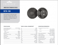
1) A factory datasheet for an Eminence driver
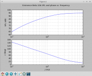
2) A calculated free-air frequency response for that driver when driven from a solid-state amplifier with essentially zero output impedance
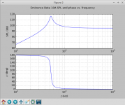
3) A calculated free-air frequency response with the speaker driven from an amplifier with a 50-ohm output impedance (which is in the ballpark for a typical 15 W push-pull valve amp with no negative feedback).
The enormous difference between the two frequency responses is clear to see.
This particular speaker is too heavily damped for free-air use when driven by a solid-state power amp; no surprise, since it's designed to be used in an appropriate sealed or ported cab. In free air, even though Fo is a low 53 Hz, acoustic response starts to fall off below about 120 Hz. In the proper size sealed (or ported) cab, the bass response will flatten out and extend lower.
When driven by a 50 ohm source impedance, on the other hand, the "Q" of a speaker rises from Qts to nearly Qms, because there is effectively no remaining electrical damping from the currents induced in the voice coil. There is only mechanical damping (from the losses in the cone surround, spider, and "goop" applied to damp the edges.)
For this speaker, Qms is around 8. A Q of 8 doesn't give you a broad, gentle bass hump. Instead, it gives you a tall narrow spike in the frequency response. This is not going to blend nicely with any kind of open-back cab; no matter what you do, you will get boomy "one note bass" at about 55 Hz.
To behave even reasonably well when driven from a 50 ohm source impedance, a speaker needs a very low Qms, with a value of, say, 1.5, or 2. This would require a *lot* of mechanical damping in the spider and cone surround.
I don't know if traditional guitar speakers really do have such a low Qms. Manufacturers never seem to publish any Thiele-Small parameters for them. (And we know why, because the high source impedance of a valve guitar amp makes nonsense out of most of the TS parameters anyway. For example, Qts and Qtc become irrelevant.)
-Gnobuddy
Attachments
- Home
- Live Sound
- Instruments and Amps
- Attenuator for a 15W to 25W guitar amp