Why not restore the lovely wooden cabinet, install a Bluetooth receiver, class D power amp, and matching power supply and speaker inside, and remove the original chassis for your guitar-amp projects? You could add a Raspberry Pi 3 and USB sound-card if you also want to listen to digital music / radio streams....making it a functional music box
<snip>
...Two good university stations...I mainly listen to them digitally.
It's the best of both worlds in some ways. You get to enjoy the lovely vintage aesthetics, and at the same time, the thing is actually useful and people will actually listen to it.
I know there is the impulse to preserve it as a museum piece, but it probably won't get much actual use that way.
-Gnobuddy
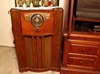
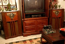
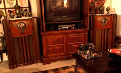
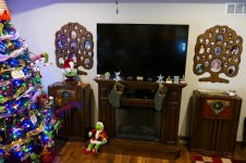
In order to come up with a set of speakers with an acceptable level of WAF, and fit into her decor, I came up with a solution. It was partially her idea when we were wandering through a flea market and she said something like, "all the speakers you make are ugly, why can't you make some that look like that".....as she points to an old console radio. Suddenly the light bulb lit up, and I said OK and bought said old radio.
Upon dragging it back home I set out to find a matching radio. Having one 1941 vintage Zenith radio was easy, now what are my chances of finding another one that looks similar? The odds were slim, but a quick look at Ebay turned up an IDENTICAL radio in "working condition" a few miles from my house.
I make the arrangements and meet the seller at his house. As I walk in the radio is indeed playing music and has a nice pair of 6V6G's tubes inside. I buy the second radio.
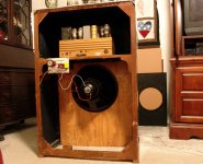
I carefully removed the original field coil speakers, the wavemagnets (rotating antennas) and the front board that the speakers are mounted on, package everything and store it for possible radio reassembly in the future. I cut some new front boards with new grill cloth and mount a 15 inch Hawthorne Silver Iris coaxial driver on each board and install them in the radios. The crossovers are mounted to the back of the radios.
!0 years and two moves totaling 1100 miles later they are still rocking. With 96 dB efficiency, and 150 watts power handling, I mean ROCKING!
Upon dragging it back home I set out to find a matching radio. Having one 1941 vintage Zenith radio was easy, now what are my chances of finding another one that looks similar? The odds were slim, but a quick look at Ebay turned up an IDENTICAL radio in "working condition" a few miles from my house.
I make the arrangements and meet the seller at his house. As I walk in the radio is indeed playing music and has a nice pair of 6V6G's tubes inside. I buy the second radio.
I carefully removed the original field coil speakers, the wavemagnets (rotating antennas) and the front board that the speakers are mounted on, package everything and store it for possible radio reassembly in the future. I cut some new front boards with new grill cloth and mount a 15 inch Hawthorne Silver Iris coaxial driver on each board and install them in the radios. The crossovers are mounted to the back of the radios.
!0 years and two moves totaling 1100 miles later they are still rocking. With 96 dB efficiency, and 150 watts power handling, I mean ROCKING!
Attachments
I second the motion.Those are nice.

Our TV is flanked by a pair of Alesis studio monitors. They're nowhere near as pretty as 1940's electronics furniture, but my wife puts up with them because she knows the sound quality really matters to me.
-Gnobuddy
I couldn't help it. Another $20 console radio although this one is a little rough. Do I need another low wattage single ended project? I have enough transformers. The PT seems rather large for the 6AQ5, OT is average. Seen these speakers before, might even have another one somewhere. For a quick project. the speaker had a covering on it and the cone looks like new.

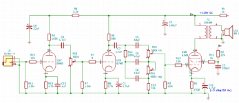
Here's an update on my 6JW8 mini-amp schematic. It's beginning to look more like a real amp schematic.
I still have tweaking to do. Bass doesn't overdrive gracefully now, as there is some audible blocking distortion. I don't yet know exactly which part of the circuit it's coming from.
-Gnobuddy
I still have tweaking to do. Bass doesn't overdrive gracefully now, as there is some audible blocking distortion. I don't yet know exactly which part of the circuit it's coming from.
-Gnobuddy
Attachments
Yeah, that must be it.From my untrained eye I would say R? might be the culprit.")
An annoying thing about Kicad - it doesn't keep track of resistor names you've already used (R1, R2, etc), so you have to do it by hand. Every new resistor you place is named "R?".
-Gnobuddy
Grid leak biasing an output valve won't work, I'd say.
Best regards!
Edit: My advice would be: Omit C4, make sure that the voltage rating of C5, C6, C7 is sufficient, get a 22nF cap between the treble pot's wiper and R3/R12, change R3 to 1M, and check R1 for correctly biasing the final valve.
Best regards!
Edit: My advice would be: Omit C4, make sure that the voltage rating of C5, C6, C7 is sufficient, get a 22nF cap between the treble pot's wiper and R3/R12, change R3 to 1M, and check R1 for correctly biasing the final valve.
Last edited:
Firstly, thank you for stopping by, and offering me your constructive criticism!Grid leak biasing an output valve won't work, I'd say.
The output pentode is actually cathode biased, with the control grid (G1) grounded through the treble and bass potentiometers and 33k resistor (RV2, RV1,R13.) The resistance of the chain varies from 533k to 1033k depending on the setting of the bass pot; even the max value is essentially within the datasheet max of 1 meg ohm.
The 10 meg resistor (R3) is only there to make sure there is still a ground reference for the pentode control grid even if the treble pot becomes "scratchy" over time, and the wiper intermittently loses contact with the resistance track.
The reason for this slightly unusual arrangement is that my LTSpice simulation showed that the bass response of my tonestack is severely damaged by 1M loading - but it's happy feeding a 10M load. This is because of the rather high-value 500k pots in the tonestack.
So why use 500k pots in the tonestack? The best reason of all - I already had them in the parts-bin!
I can't do that, as C4 is part of the tonestack. The treble control won't work without it.Omit C4
This tone-stack is also sensitive to capacitive loading at the output - the treble control would not work well feeding a typical half-12AX7 with 100 pF input capacitance. But here, it works fine, because it's feeding a pentode with a datasheet input capacitance of only 3.2 pF (from G1 to all other electrodes.) It's the magic of the screen grid!
While I can't eliminate C4, I think I did eliminate C7 on the breadboard. It's not needed, as C4, C5, C6 isolate the anode of the 6JW8 triode from the rest of the circuitry.
Definitely! They are all rated 250V DC or higher. B+ is only 135V DC for this circuit....make sure that the voltage rating of C5, C6, C7 is sufficient
I need the direct DC connection - that's how the pentode gets it's ground reference, through the treble pot.get a 22nF cap between the treble pot's wiper and R3/R12
This completely messes up the bass control response in the LTSpice simulation. Fortunately, R3 isn't doing anything at all as long as the treble pot is working properly (wiper is making contact internally.)change R3 to 1M
Agreed! DC current and voltage checks matched the design operating point quite well, but I will hook up a signal generator and look at how the pentode clips as well. I'm waiting for a 100:1 'scope probe to arrive in the mail.and check R1 for correctly biasing the final valve.
Thanks again for the comments!
-Gnobuddy
I got my 100:1 'scope probe, so tonight I did some checking with an AF signal generator and 'scope....and check R1 for correctly biasing the final valve.
The output pentode turned out to need no changes. As I turn up the signal level, it starts to clip equally on both positive and negative halve-cycles at the same time. So it's already centre-biased.
The triode section of the 6JW8, however, turned out to be cold biased. Positive peaks at the anode clipped well before negative ones. So I did some tinkering with the cathode resistor (R6, originally 2.7k), and settled on 1.8k as the new value.
This change improved the overdrive quality. It's now a bit more progressive, and smoother / less harsh as it begins to enter breakup. Keep in mind my threshold for "harsh" is lower than most guitarists today.
This little amp is bright, in a sort of typical SE pentode way. I find myself setting the treble control to minimum all the time, so it may be time to look at some changes to the tone stack, or maybe I should put in a little treble roll off somewhere else.
Overall, it's a nice little amp. Clean tones are loud enough for an apartment, overdriving the output is really a bit too loud. Amazing what a whole thundering quarter-watt of raging power will do!
The attached partial schematic shows the only change I made today. The rest of the circuit is exactly as it was the last time I posted a schematic.
Drat. I just spotted a minor error: C7 has been removed, and shouldn't be in the schematic.
-Gnobuddy
Attachments
maybe I should put in a little treble roll off somewhere else.
Try a small pF cap, or series cap and resistor pair from the output tube grid to ground. I got this idea from some popular P-P amp that wired a "cut" control (pot and cap in series) from output grid to output grid in a push pull amp. I used it in some of my "Turbo Champ" SE amps in the late 90's to smooth out the racket when using coaxial or triaxial car speakers. I think the cap was 470 or 1000pF maybe.
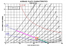
My secret weapon for asymmetry is the extremely non-linear triode in the 6JW8. Take a look at the attached image - look at the enormous difference in output swing for positive and negative half-cycles!So a little bit (according to each one's taste) of asymmetric limitations may be welcome.
Biased at Vgk=(-3V), and with the 300 volt B+ and 50k anode load shown in the figure, if the input swings positive by 3 volts, from Vgk = (-3V) to Vgk = 0V, the anode (output) swings negative by nearly 150 volts.
But if the input swings negative by the same 3 volts, from Vgk = (-3V) to Vgk = (-6V), the output swings positive by only 80 volts!
In my mini-amp the asymmetry is not quite as drastic as in this image, because of the lower B+ voltage and different load-line. But on the oscilloscope, I can still see plenty of asymmetry at the anode as the input sine wave amplitude is slowly turned up.
Best of all, the asymmetry starts to develop long before there is any actual clipping (flattened tips to the signal). This means there is a progressive increase in distortion, starting from very clean, until full clipping begins.
I'm definitely having fun with this little thing. I almost want to build one as a stand-alone guitar amp head to plug into any guitar cab, and a second one for the original purpose of this thread: as a signal-sweetener box that goes between guitar and P.A. system.
I prefer the sound of guitar amp distortion after it has been sweetened by a little reverb, which will be much easier to do with the DI-box version. So I suspect the signal-sweetener box may end up sounding better than the small guitar amp head.
-Gnobuddy
Attachments
Thanks for the suggestion!Try a small pF cap, or series cap and resistor pair from the output tube grid to ground.
I may have to move such a cut network to the anode of the triode, because the tweaked Fender tone control I'm using is very sensitive to capacitive loading at the output. The treble control becomes ineffective (in LTSpice simulation) if the output is loaded with more than a few pF. Putting 100 pF loading on the output knocks the treble control range down by about 5 dB at 4 kHz.
This tone control is also sensitive to resistive loading (which reduces bass control range). I'm running it direct into the control grid of the pentode, so there is very little resistive or capacitive loading seen by the tone control.
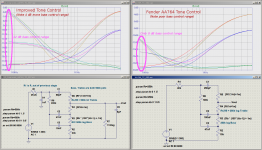
Speaking of control range, the attached image shows where I started (a stock Fender AA764 Champ tone control). It also shows where I ended up, and the performance difference predicted by LTSpice between the two circuits.
Incidentally, I didn't change the vertical axis scale to make my tone control circuit look better...LTSpice did that automatically, and I didn't notice until I'd finished processing the image to post here. But the correct numbers are shown on the image - the tweaked circuit really does have 4 dB more bass control range at 80 Hz than the version Leo used in his Champ.
-Gnobuddy
Attachments
Biased at Vgk=(-3V), and with the 300 volt B+ and 50k anode load shown in the figure, if the input swings positive by 3 volts, from Vgk = (-3V) to Vgk = 0V, the anode (output) swings negative by nearly 150 volts.
But if the input swings negative by the same 3 volts, from Vgk = (-3V) to Vgk = (-6V), the output swings positive by only 80 volts!
So how many dB difference is 150V to 80V?
I believe you are missing the point by a country mile (or a country 1.60934 km, since we are in Canada.)So how many dB difference is 150V to 80V?
We're talking about positive and negative half-cycles of the same waveform being very different in size - in this case, nearly in a 2:1 ratio.
You don't hear this as decibels, which are used to express changes in average amplitude of a steady-state signal. You hear this as harmonic distortion.
The question is, how much harmonic distortion? Enough to hear?
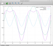
A quick test with a spread-sheet (and another with the wonderfully useful Gnuplot plotting program) show that it takes about 40% pure second harmonic distortion to make a sine wave so lopsided that one set of half-cycles is half as big as the other. Yes, 40% THD is very, very audible!
The attached image is from Gnuplot; the green curve is sin(theta), the pale blue curve is 40% pure second harmonic (0.4*cos(2*theta)), and the purple curve is the result of summing them. As you can see, the purple curve goes up to approximately +0.75, but negative half-cycles go to nearly -1.5. This roughly emulates the 2:1 amplitude ratio produced by the 6JW8 triode operating just this side of actual clipping.
By contrast, it is tough to get even 10% second harmonic distortion out of a half-12AX7 without clipping it outright (which means flattened tips of the waveform and a much harsher timbre.)
So the fifty-cent triode in a 6JW8 is capable of generating a lot more smooth, not-harsh, not-clipped, distortion than the ubiquitous half-12AX7. (The flip side being, you will never get a truly low-THD signal out of the 6JW8 triode.)
I think this is particularly useful in low-volume amps like this one. At low SPL, our ears are not as sensitive, and I find I want more distortion in the "clean" signal to keep it from sounding sterile-solidstate-clean. At high volumes (Fender Twin), we need far less THD to hear a change in tone, so the 6JW8 triode might be far too much colouration for a 'Twin clean tone.
-Gnobuddy
Attachments
Pure second harmonic adds a new note exactly one octave above the original note. This will change the apparent timbre of the note without imparting any dissonance. Thus second harmonic distortion when applied to a single note (lead guitar) can be tolerated in fairly large amounts. This applies to a lesser degree to all even harmonics. Harmonic distortion rarely comes to the party alone though, it usually brings its ugly friend, IMD.
IMD almost creates dissonance because the mixing products rarely fall on musical intervals. This is where "power chords" come in handy. They are mathematically created such that the primary IMD components are less dissonant, and are usually limited to 2 or 3 notes.
I was getting similar "stretched" sine waves by playing with the screen voltage in a pentode gain stage.
- Status
- This old topic is closed. If you want to reopen this topic, contact a moderator using the "Report Post" button.
- Home
- Live Sound
- Instruments and Amps
- Mini-amp for Output Tube Distortion