I liked the originality of Nachbaur's designs. You could tell he knew what he was doing, too. No faffing about with magic capacitors and unicorn-earwax insulation for him - he designed like a real engineer, and was a real musician too. Quite a guy.Fred Nachbaur kept the transformer in the small-amp-emulator for his Dogzilla amp.
I can't connect to Nachbaur's (memorial) website now, I find. I wonder if someone stopped paying the hosting bills? I think poor Nachbaur passed away in 2004 and a copy of his website has been hosted all these years as a memorial to him.
My suspicion (and it's only a guess) is that using a small, low quality output transformer in Dogzilla might have filtered out both unwanted high treble, and unnaturally deep low bass. In other words, I suspect it was there more to act as a crude speaker emulation filter than because the OT itself contributes something useful to the sound.
If the small low-quality OT is discarded, one is going to have to put some effort into a proper speaker emulation filter. This seems to be the one thing that is hardly ever done in DIY guitar projects, though the big guys (Zoom, Digitech, etc) certainly include them in their little digital buzz-boxes.
I suspect we amateurs have stayed away because analogue filter design has been complex and heavily mathematical in the past. Sure we could look up some tables and throw together, say, a 4th order Chebyshev low-pass filter with 1 dB ripple and a 3 kHz cut-off frequency. But that doesn't look anything like a guitar speaker emulation filter!
And, of course, the electronics textbooks don't have tables showing how to turn a Chebyshev into a guitar speaker emulation filter.

Fortunately for us, LTSpice (and other similar sim software) has almost knocked down that particular wall. Now we can start with a textbook filter, simulate it in LTSpice, and use some educated guesses and some persistence to tweak values until the simulated frequency response starts to look like a proper guitar speaker emulation filter.
I happen to have a 25k SE transformer in the junk-box, otherwise I'd have tried that.I was also thinking you could discard half your power and put a 10K transformer in series with a 10K or 15K resistor, which might increase the range of options.
For this application (tiny amp-in-a-pedal for direct to P.A. use), it would be really nice to get rid of the weight, bulk, and expense of the OT altogether, though.
-Gnobuddy
I still have this project on my bench, one day. Got two of the Peavey's going, should fix up the third today. Wasted a lot of time stripping organs of their guts, no shortage of 8 and 9 pin sockets. Could use some 7 pin ones though. Also have a life supply of neon bulbs to limit the startup voltage on cathode follower grids.
Also noted how the arm and belly cut on the Peavey's were more comfortable than a Telecaster so I shaved down the areas on my pine and poplar guitar. Looks like hell because the finish that was on the body was more of a golden colour and I only have clear in the house, looks odd. Oh well, I am more concerned with making it playable for the time being. Got to finish some guitars yet. I gave an early one to a guy at work to put on the wall and his 11 year old girl jumped on it like a cat on a mouse. He showed me a picture of her with it and her eyes are all lit up. Seems I am going to be making her a guitar at some point, maybe in the spring.
Also noted how the arm and belly cut on the Peavey's were more comfortable than a Telecaster so I shaved down the areas on my pine and poplar guitar. Looks like hell because the finish that was on the body was more of a golden colour and I only have clear in the house, looks odd. Oh well, I am more concerned with making it playable for the time being. Got to finish some guitars yet. I gave an early one to a guy at work to put on the wall and his 11 year old girl jumped on it like a cat on a mouse. He showed me a picture of her with it and her eyes are all lit up. Seems I am going to be making her a guitar at some point, maybe in the spring.
I think this is a cool little project.
I actually just use a 2w valve amp for my guitar (Vox Lil' Night Train) - 2x 12AX7 for gain stages, and then a 12AU7 in push-pull for the output stage. Sometimes I swap another 12AU7 into the gain stage to tone it down a bit - with that, there's enough to get some nice overdrive at full gain, without it getting messy.
It's pretty loud through a good 1x12" cab, although some extra attenuation would be nice for home use.
FWIW, the output stage topology will change the breakup sound somewhat, but I really like what that push-pull output stage does.
I believe schematics are available online. The cap mod (disconnecting a cap that's boosting HF) is pretty mandatory.
Chris
One of my first valve projects was a DIY two-watt guitar amp using a push-pull pair of 6AK6s for the output, and two 6JW8s in the preamp. It has two channels, and separate tone controls for each channel.
My PP 6AK6 amp was originally inspired by a PP 6AK6 amp that Printer2 designed and built. His was a "Mini 5E3". At the time, I had been looking for small pentodes that I could use to build a low-power guitar amp, but had no experience with valves at all, and the only valves I'd ever heard of were the 12A*7 family, 6V6, 6L6, and EL84.
My goal this time is to build something much smaller and lighter than a 2W combo guitar amp, something that will put out a line-level signal to feed the P.A. system with.
I already play my guitar straight into the P.A., with a few FX pedals in between. I can get acceptable distortion from pedals. What is lacking is "valvey" cleans, so that is what I want first and foremost from this project. In a small and simple package, if possible.
Judging by his initial schematics, I suspect Printer2 is after something rather different, more like a full guitar amp squashed down to small size and weight.
Though I've posted initial ideas around the concept of a few-hundred-milliwatt SE guitar amp using a small-signal pentode, on reflection, I don't really have a good idea of the best way to start. With a little pentode? With a small-signal triode? With a JFET/MOSFET cascode? With the surprisingly good12AX7-triode emulation MOSFET gain stage invented by a Russian engineer who goes by KMG on the forums?
I agree that SE and PP output stages tend to sound different. It is easier* to lose the output transformer with a single-ended topology, so SE is where I plan to start.
*It may be possible to get rid of the OT and still do push-pull, by attenuating and then combining the signals at the two output anodes using a differential amplifier stage. A centre-tapped OT primary essentially inverts one signal and then adds the two signals together. This is also what a differential-input amp (long tailed pair or op-amp) does!
-Gnobuddy
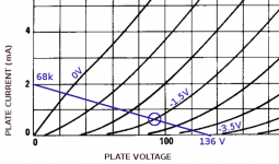
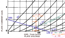
A bit more progress to report. It looks like the triode in the 6JW8 can also be coaxed into working with a relatively low 135 volt B+ rail, as the attached load line shows.
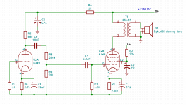
This is the same supply voltage I used for the pentode part of the 6JW8 in the preliminary schematic I posted earlier, which is convenient.
With a little careful juggling, this value of B+ also allows a quiescent operating point at Vgk = (-1.5V). This is about the same value of Vgk found in all those "classic" 12AX7 gain stages in Fender amps.
The chosen load-line also puts the 6JW8 triode into cut-off at roughly Vgk=(-3V), which is also similar to what you get from a typical half-12AX7.
Hopefully this means the input stage will have overload characteristics roughly similar to the usual stage made with a 12AX7 and 100k and 1.5k anode and cathode resistors respectively.
Estimated voltage gain of the triode stage is around 30 times, about half what you'd get from a 12AX7 gain stage running on 300 volts.
We've estimated the little pentode stage only needs 2.5V peak-to-peak to drive it to full clean output. So we might need quite a lot of attenuation in between the two stages, to allow the triode stage to be driven hard enough to provide some valvey distortion of its own.
This inter-stage attenuation will be chosen for best tone, and not to generate the desired voltage gain. The valves are there to be tasty tone generators, not voltage amplifiers; any voltage gain they produce is just a nice by-product. If extra (clean) gain is needed, it's easy to stuff a MOSFET or two wherever necessary. This is a luxury that Leonidas and Jim and their techs did not have back in the era of the classic valve guitar amps.
Speaking of MOSFETs, there is a phasing issue I'm pondering. The triode stage will distort in such a way as to output bigger negative half-cycles than positive ones. Since the following pentode stage inverts, this means the triode will try to make the pentode put out bigger positive half-cycles.
However, the pentode by itself has more gain at higher anode currents, which means it tries to generate bigger negative half-cycles than positive half-cycles.
So if the distorted triode output is fed into the pentode, there is a conflict. The triode is trying to make the pentode spit out bigger positive half-cycles; the pentode itself is trying to spit out bigger negative half-cycles. This means some of the distortion will be cancelled out because the two stages have opposite kinds of nonlinearity.
So there may be a case for sticking an inverting stage between the the triode and pentode. It doesn't need to have more than unity gain, or produce any distortion of its own. The obvious answer seem to be the use of a MOSFET "source-o-dyne" stage.
Is this a good idea or a bad one? I think this one will have to be tested by ear.
-Gnobuddy
Attachments
> a case for sticking an inverting stage between the the triode and pentode.
Fender AA Champ. At high input, the first triode and the 6V6 distort the same way, ~~5% each; the 2nd triode is not working hard (note heavy tonestack here) and has low distortion (~~1.5%).
Fender AA Champ. At high input, the first triode and the 6V6 distort the same way, ~~5% each; the 2nd triode is not working hard (note heavy tonestack here) and has low distortion (~~1.5%).
Last edited:
Excellent point. Thanks for that!Fender AA Champ. At high input, the first triode and the 6V6 distort the same way, ~~5% each; the 2nd triode is not working hard (note heavy tonestack here) and has low distortion (~~1.5%).
I hadn't really been thinking about tone controls yet, but it would make sense to stick them between the two stages to provide the attenuation that is necessary there.
If I stick a MOSFET in between to provide phase reversal, maybe it can also do something useful (such as implement a separate mid control.)
-Gnobuddy
The small-tube-amp-thingie to add tube flavour and grit is usually a DIY thing, but there was *one* Commercial unit designed to do that, a basically Champ amp designed NOT to drive a speaker but to be used as a floor pedal or in an effects loop, the Canadian Garnet Herzog, designed for none less than Bachman Turner Overdrive.
Hey, the band name should have given a clue, wouldn´t it?
Hey, the band name should have given a clue, wouldn´t it?
Attachments
I heard about the Herzog a few years ago. The Guess Who and Bachmann Turner Overdrive weren't staple listening for me when I was young, so I had to go back and listen to "American Woman" to remind myself what the famous Herzog (plus big guitar amp) sounded like.the Canadian Garnet Herzog, designed for none less than Bachman Turner Overdrive.
One thing that strikes me is that there is very little harshness in the distorted, sustained, Herzog-processed lead guitar sound. I don't see anything in the Herzog schematic to limit harsh treble, so am curious how the eventual tone coming out of the big amp was so mellow.
Did Randy turn the treble on the main amp down to zero, or was it the recording engineer who filtered out all the Champ harshness before the signal hit the tape recorder?
Thoughts of the Herzog were floating somewhere in the back of my head when I first responded to this thread. If "Gar" Gillies made a real Fender Champ into a Herzog, why shouldn't I make a sort of "micro-Champ" out of a 6JW8, and use that instead of a 12AX7/6V6 pair?
I had social obligations today that kept me from the electronics workbench, but I found a few minutes to estimate the triode parameters of the 6JW8 triode around the operating point I plan to use.
I wanted to know the anode resistance, so I could estimate the gain stages output resistance, so that I can plan for that when designing the tone controls. Having found ra, I figured I might as well also estimate mu and gm. They are in the attached image.
-Gnobuddy
Attachments
I don't know how far along anybody is with actually building anything, but I offer this chart to help.
I usually start a project by digging up all the information I think I will need up front so I don't wind up doing something over because I found a better way halfway through the design. Since I tend to make lots of tube things and have the brain of an engineer, powered by a case of OCD and ADD, I sat down nearly 20 years ago and condensed the information found in several tube manuals and countless web pages into a large Excel spread sheet. I grouped tubes together by function and sorted out the tubes that have compatible pinouts. This spreadsheet is a work in progress, but is getting reasonably mature. The last update was January 2018. Sometimes a new project will create a new page.
This is the page created for the Hundred Buck Amp Challenge triode / pentode concept. There are hundreds of different triode / pentode tubes in every possible base. There are two groups of tubes with compatible pinouts in the 9 pin base that have separate cathodes.
The top group has two different "EIA bases" (9AE and (DC) but the pinouts are the same. These are PIN compatible, they can be swapped without smoke due to wiring errors, but may NOT be electrically compatible without parts value changes. Note that there are no tubes with a 12AX7 triode section.
The second group is also pin compatible within its group (all 9DX). It is NOT compatible with the first group. These tubes tend toward higher Gm and power dissipation in the pentode section, and there are two with 12AX7 triode sections, the 6EB8 and the 6GN8. There is another with a similar triode with slightly higher Gm, the 6KT8.
If you are looking for a single tube design for maximum gain, the second group is where to look.
Note that I had some bad luck trying to use some of the tubes in the first group for preamp duty with the pentode driving the triode back in the HBAC. The pinout puts the output right next to the input making for some good oscillators.
Attachments
I couldn't help but hear the Guess Who and Bachmann Turner Overdrive in the day. I never was into building amps otherwise I would have paid Gar a visit. Well I did once to see about getting a speaker re-coned but he left the building a few years before I go into this.
Just letting the fingers get some heat in them, I should have done this while it still was above freezing. Cleaning out the garage so I can get my car in it. Now if I didn't have a shed that flooded every spring I would have room to put some of this stuff in.
Just letting the fingers get some heat in them, I should have done this while it still was above freezing. Cleaning out the garage so I can get my car in it. Now if I didn't have a shed that flooded every spring I would have room to put some of this stuff in.
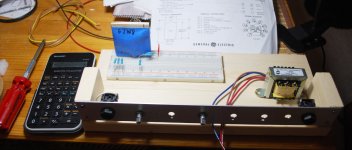
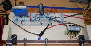
Not far. Just beginning to prototype on a breadboard. See attached breadboard pic.I don't know how far along anybody is with actually building anything
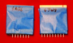
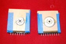
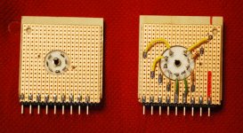
The other pics show a pair of valve-to-breadboard adaptors I made recently. Legal disclaimer: these adaptors are not safe to use at the voltages valves need, so please don't copy mine. I was dropped on the head one too many times as a baby, that's my excuse.
With a little luck I might get to apply power tomorrow, and at least check out DC operating conditions. With a little more luck, maybe I'll have enough time to put the signal generator and 'scope to work for initial AC measurements.
Thank you!but I offer this chart to help.
I found the 6LX8 on a dollar list a year or so ago, and looked up the datasheet. It appears to be identical to the 6JW8 datasheet in every detail, except for the numerical designation. I'm not sure what that's about.
I have some 6LY8s, and 6HZ8s, both of which appear to have a half-12AX7 for the triode. I imagine either one might be useful to make a Herzog.Note that there are no tubes with a 12AX7 triode section.
<snip>
If you are looking for a single tube design for maximum gain, the second group is where to look.
A couple of years ago I worked out how to use a 6JW8 in the preamp of my little 2-watt PP 6AK6 guitar amp, and it does a good job there.
But the little pentode in the 6JW8 is so low-rated (1.2 watts anode dissipation) that I didn't really expect it would work as a SE power amp with an off-the-shelf OT, able to actually drive a speaker. To my surprise, when I started playing around with load lines, it all came together.
I'm not too worried about voltage gain. All I want from the tubes is tasty distortion. If I need additional gain to allow the tubes to reach their full sonic potential, I have a fistful of LND150 MOSFETs somewhere around here...
I'm probably asking for trouble sticking one in a solderless breadboard, then. We'll see how it goes!The pinout puts the output right next to the input making for some good oscillators.
-Gnobuddy
Attachments
At a previous job, there was a shelf loaded with NOS valves left over from an long-defunct electronics tech program. I could probably have got them for the asking - but at that point I still didn't have the faintest idea that valves were the cure for my years of awful electric-guitar tone. So I didn't ask for them, and one day they disappeared - most likely gone to the crusher, I was told.I never was into building amps otherwise I would have paid Gar a visit.
We have been lucky, we just had a couple of days of sunshine, which is a rare thing in southern BC at this time of year - it's normally months of grey skies and cold drizzle.Just letting the fingers get some heat in them
I went for a walk in a regional park within easy driving distance, and took a few pics. There are still leaves on some of the trees and bushes.
There is a story about the picture with the little blue boat. I saw a small log floating down the river, then this little boat came tearing across the water, chasing after the log. The boat pulls up alongside the log, the fellow in the boat leans over and hammers a spike into the log, ties a rope to the spike, and then heads happily back, log in tow.
-Gnobuddy
Attachments


making for some good oscillators.....I'm probably asking for trouble sticking one in a solderless breadboard
If you are using the triode to drive the pentode, then the pinout works in your favor, since the triode plate is next to the pentode grid. Going the other way with conventional common cathode stages makes oscillators since it puts two in phase signals with a bunch of gain right next to each other.
tearing across the water, chasing after the log......heads happily back, log in tow.
It must have been a very special log, rare tone wood perhaps...
Life keeps getting in the way, but I found a few minutes to solder and wire today, in between feeding the cats and cooking dinner. The Hammond OT is now mounted securely on a small pine plank carrying the breadboard, and it's wired up to a 1/4" speaker jack. The primary is also wired up to the appropriate places on the breadboard.Oh, just build it and post results
All it needs now for initial DC operating point testing is a supply rail filter cap, and heater and B+ power to be connected. Maybe tomorrow.
-Gnobuddy
Good point. My taped-over Veroboard tube-to-breadboard adaptor hid this from me on the breadboard.If you are using the triode to drive the pentode, then the pinout works in your favor
Right now, the triode and pentode are completely independent on the breadboard. Once DC operating points check out, I'll add coupling caps for AC operation.
-Gnobuddy
I got as far as applying power and doing a few DC checks today.
It took 1.5 ohms in series with the heater to drop the 7.3 V RMS (!) from the supposedly 6.3V transformer down to an actual 6.3V RMS, as indicated by my DMM.
But that was the only unpleasant surprise. All other voltages and currents checked out remarkably close to the numbers I'd estimated from the load lines.
For the pentode Vgk settled down to (-1.54) volts across the 270 ohm cathode resistor. Cathode current is 5.7 mA, and screen grid current is about 1.23 mA, so anode current must be 4.47 mA. Right on the money, though Vg2 measured 108V instead of the 100 V I was shooting for.
The triode also biased up nearly exactly as expected: Ia=560 uA, Vgk = (-1.505 V).
I've plugged in a roughly 6" driver from an ancient thrift-store Sears speaker. There is a little audible buzz, not too surprising with no metal enclosure, AC heater power, and a quick-n-dirty power supply.
Touching the control grid of the pentode with a fingertip makes the buzz considerably louder. So we definitely have enough gain and output power to make at least a little noise with a speaker. And this is just the pentode - the triode stage hasn't even been AC-coupled to the pentode stage yet.
I guess the next step is to couple the triode output to the pentode input, wire up the input jack, and just for fun, see if there is already enough gain to play guitar. With no tone-stack losses, I expect there will be.
I still find it amazing to be using a 1.8 megohm resistor in series with the power indicator LED. It's nice and bright at 100uA LED current, instead of the 10,000 uA we would have had to use just a decade ago!
-Gnobuddy
Attachments
I just did that, and yes, there is. In fact there is enough gain to get just a little grit on the sound if you strum a six-string chord on a guitar with humbucking pickups.I guess the next step is to couple the triode output to the pentode input, wire up the input jack, and just for fun, see if there is already enough gain to play guitar.
With the unbaffled, decades-old, thrift-store driver that came out of a box labelled "Hi-Fi", the volume was ample for midnight apartment playing. Maybe a bit too much.
I think the next steps are:
- Plug into a better speaker.
- Add a tone control of some sort.
- Add some gain ahead of the triode to see if we can get a little musical nonlinearity out of the triode itself.
- Add a phase inversion between triode and pentode to see if that enhances their combined sound.
-Gnobuddy
- Status
- This old topic is closed. If you want to reopen this topic, contact a moderator using the "Report Post" button.
- Home
- Live Sound
- Instruments and Amps
- Mini-amp for Output Tube Distortion