sup!, past weekend bought a Crate V18 guitar amp for dirt cheap, $30 (20.000 pesos chilenos), originally the owner brought me this amp to fix it, after some inspection noticed it hadnt a power supply at all, seems like someone removed it. The obvious solution is getting a new transformer, but its impossible for us, so instead of dumping it i asked him to buy it and he accepted instantly.
This amp has so much potential, also i've never had a 'serious' amp, what i could do? I thought about making a modding some transformer, but must be the cheapest possible. First I tried modding a MOT i had lying around and rewind it to get 350v, 6v and+- 12v however , just tried it today and god...that thing rattles just too much, also i read somewhere the construction of this kind of transformers is really not suitable for audio.
but what about modding an isolation transformer? they are not expensive at all, and the small ones seem good for this purpose(100 w or less)? The laminations are ok, power rating, everything sound fine to me, the only job is rewinding the secondary, what do you think about it?
OK, down here in the antipodes power supply and output transformers are bloody expensive and there's a history of work arounds.The obvious solution is getting a new transformer, but its impossible for us, so instead of dumping it i asked him to buy it and he accepted instantly.
In short, for B+ one can use:
a) back to back transformers. Works as long as your B+ isn't too high or pulling too much power
b) voltage multipliers. Take 30VAC or better and cascade your way to B+
There's no rule that says you need to pull heater from the same iron as the B+ either. Use multiple bits of iron to get the voltages you need.
A particularly clever example is GC Will's SOLO but also look at his Lamington 15W- it'll be very close to what you need for 18W
The images below are his.
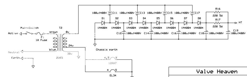
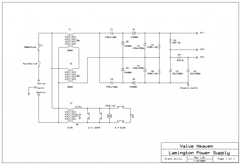
So the original SMPS made +320v, +6.3v, and +/-17v.
SO you need a transformer making about 225vAC, plus the heaters, and if not the same transformer, at least one that will make a pair of 15v supplies.
How about Fender, can you get Fender iron? A Blues Junior ought to be close.
SO you need a transformer making about 225vAC, plus the heaters, and if not the same transformer, at least one that will make a pair of 15v supplies.
How about Fender, can you get Fender iron? A Blues Junior ought to be close.
So the original SMPS made +320v, +6.3v, and +/-17v.
SO you need a transformer making about 225vAC, plus the heaters, and if not the same transformer, at least one that will make a pair of 15v supplies.
How about Fender, can you get Fender iron? A Blues Junior ought to be close.
Maybe but that would be expensive, fender chile goes nuts for prices
Hey thanks for the reply guys, thoglette i think i'd go for a) because i already got a transforner, yesterday bought an 220v/110v transformer for cheap so i just take it a rewind it, my only issue is my little experience on this matter and the small gap beetwen the core an the bobbin, that space seems so small for a secondary over it. Gotta show you some pics


Chile has 220V AC mains, yes? If you plug the 220 V side into the wall outlet, and use a voltage doubler (two silicon diodes and two filter caps) on the 110 V secondary, you will get somewhere between 330V - 360V DC....I already got a transforner, yesterday bought an 220v/110v transformer
That may be a little less than the original power supply voltage, but it should make enough power from the amp to have fun with.
")
As for the other lower voltages - why not look for second-hand switch-mode DC power supplies? I'm not sure what these cost in Chile, but if you can find an affordable one with a voltage a little more than 6 volts, and a big enough current rating, you can run the heaters from it. Just insert a suitable power resistor in series to drop the voltage a little, so you have 6.3V at the valve heaters.
I use an 8.4 V, 1.8 amp, Sony power supply with a series resistor to run the heaters in one of my amps. The power supply was found in a thrift-store, and I think I paid $2 for it, because of the oddball voltage (nobody else wants an 8.4V supply.)
You can take the same approach for the +/- 15V or +/- 12V rails. For example, many Hewlett-Packard inkjet printers use a three-wire power supply that delivers 0V, +16V, and +32 V to the printer. When the printer fails, people throw away the power supply or give them to thrift stores. Around here, you can find them very cheap. Maybe in your area as well?
The DC output of these HP printer power supplies (at least, all the ones I've seen that have a two-pin AC mains plug) is completely isolated from the AC mains side. So, if you ground the +16V wire, you now have -16V, 0V, and +16V rails - perfect for op-amps!
I have used one of these in a home-made op-amp audio project, and with a little extra filtering on the +/- 16V rails (small series resistor and 100 uF electrolytic cap to ground), it works very well.
-Gnobuddy
Chile has 220V AC mains, yes? If you plug the 220 V side into the wall outlet, and use a voltage doubler (two silicon diodes and two filter caps) on the 110 V secondary, you will get somewhere between 330V - 360V DC.
-Gnobuddy
Yes, here is 220v. I thought the same before i dissasembled the transformer, but the thing is actually an autotransformer, is not isolated. Just adding a multiplier would have been super easy...
Now i have other issues, i also dissasembled the primary thinking i could rewind it more compact, but the results werent the expected, i dont have tools for winding transformers so i was doing it by hand, I had to stop at half way beacuse the thing wasnt looking good as it was the size as the original.
Also it was difficult to coil because the bobbin had no edges, making harder to coil without wasting space.
Seems like i have to spend for a new primary with smaller gauge for more space and less power(it was originally 125-ish W) above 40 watt would be fine i guess.
I tried the same thing many years ago, when I was still a boy. I had no success either. I could not wind the coil as neatly by hand, nor stuff the laminations as tightly. And the sharp metal edges cut my fingers, so I left some blood behind in the (badly) wound transformer.i also dissasembled the primary thinking i could rewind it more compact
-Gnobuddy
I tried the same thing many years ago, when I was still a boy. I had no success either. I could not wind the coil as neatly by hand, nor stuff the laminations as tightly. And the sharp metal edges cut my fingers, so I left some blood behind in the (badly) wound transformer.
-Gnobuddy
LOL
Past week was for getting the materials and a planning everything for the transformer
Making the transformer was a painful experience. First despite the difficulty to coil the thing by hand, noticed the space was limited again even with 24 AWG(was AWG 20 or so before) so were no room for heaters and the 12-0-12 for the solid state stuff, had to use a separate transformer for that purpose. At the end the tranny got super thick and the wires where almost touching the iron in between, looking like ****, i call it the potato transformer lol.
Also, something i had not mentioned, before finishing it got wrong voltages, my calculations where not precise enough and had 203v at the beginning... ran out of wire and had to improvise a bit, good thing i had another tranny with 24 awg inside and cannibalized it. After trial and error, added more turns until i get close to 230 -240v, got 233v at the end, close enough.
The separate transformer was easier though, i had everything at home and took an afternoon to make it, picked some 12v 3A transformer and rewinded it for the heater supply the 12-0-12, however the voltages were a bit off again. i got 7.2V for the heaters(center tapped), i know this is way off, any suggestion to fix it whitout dissasembling it? I was thinking of shottky diodes and chopping of some voltage.
Yet i cant test anything until i get one EL84, also i have to make the pcb for the rectifier and the filtering. also i have to plan how to fit the stuff inside, but that job will be for the next week.
After all im happy because it was the hardest step, the rest is going to be much easier. Thanks for all the suggestions guys
Gotta upload some pics
I have a crate V-33 with a faulty power supply board, I experienced a power surge off my Variac
Last edited:
I would avoid diodes, they will add a lot of noise to the heater current because of the sharp-cornered current and voltage waveforms.I got 7.2V for the heaters(center tapped), i know this is way off, any suggestion to fix it without dissasembling it? I was thinking of shottky diodes and chopping of some voltage.
But the solution is very simple - you can use a small power resistor - it's easy, effective, and cheap.
As an example, let's say your 7.2V drops to 6.8V under load, and let's say your heaters draw 2 amps. You need to go from 6.8V to 6.3V, so you need to drop 0.5 volts. Ohms law says R = V/I = 0.5V/2A = 0.25 ohms.
So you would insert a 0.27 ohm or 0.22 ohm (nearest standard value) resistor ins series with the heater power, and that should get you the right heater voltage.
Keep in mind that the heater current may not be exactly what the factory says, and it will change slightly when you add the resistors, so you may have to re-calculate and try out the resistors a couple of times before you find just the right values.
If you are picky, you can divide the resistor into two equal values, and put one in each of the heater wires, so that the centre-tap remains accurately centred (and not slightly imbalanced by having the additional resistor on one side). In our example, you could use two 0.12 ohm resistors (divide 0.27
ohms by two, and then use the nearest standard value.)
The only remaining question is how big (power handling) the resistors should be. Power dissipation is current * current * voltage. In our example, that is 2A*2A*0.27 watts, which works out to 1.08 watts. You could use a 2 watt resistor, or a somewhat bigger one to add more safety margin. A 5W resistor would run quite cool.
If you split the resistor into two equal ones of half the resistance, the power dissipated in each one is also halved - only 0.54 watts each. So in this case you could use two 1W resistors (or better, two 2W resistors.)
I recently found an old Hammond power transformer with a 6.3V heater winding - but it put out 7.5V RMS according to my DMM! This is a common problem with older transformers in North America, because the mains AC voltage has increased quite a bit in the last fifty-odd years.
I fixed the problem exactly the same way I just described, with a small resistor in series.
-Gnobuddy
You certainly could. The amp cares only about the voltages that are applied to its wires...it doesn't care how that voltage is generated, whether old-school power supply, modern switching supply, or a large box full of lemons with wires stuck into them....Could I convert this amp power to a traditional (old school-pre 1980's) power supply?
The only real issues are that the old-school power supply will weigh five to ten times as much as the switching supply, and take up more room. I'm assuming you're okay with the weight increase, and that there is plenty of room inside the amp case to acommodate the larger power supply you're going to build.
The HT (B+) and heater power require nothing different from thousands of classic guitar amp circuits. The only thing a little different is you need to provide +15V, 0V, and -15V as well; I would suggest using a separate small transformer for this, or even a pair of small switching supplies (a very simple solution that reduces the amount of stuff you have to build.)
Alternatively, a 15-0-15 (AC, RMS volts) transformer feeding a bridge rectifier and filter cap will generate somewhere around +/-20 volts DC, which you can regulate down to +/- 15V with a couple of 3-terminal voltage regulator chips. Or you can use a 12-0-12 ACV RMS transformer, which should generate something close to +/- 16 volts DC, and you can drop that a bit more with another RC filter stage, avoiding the need for voltage regulator chips.
-Gnobuddy
There are only a few components in an old-school power supply: AC inlet, switch, fuse, power transformer, a couple of silicon diodes, a filter capacitor. If you have previous experience building tube amps, the power supply itself is pretty easy to build - but remember that safety is all-important. Both your own safety while building and testing the power supply, and the safety of anyone else who might use the amp in the future.So where can I find a diy to build? Thanks
So, if you have no previous experience building electronics, a high-voltage power supply is not the place to start. There are lethal voltages involved.
If that is the case, why not talk to your local tube amp tech? He/she should be able to put together a power supply for your amp.
-Gnobuddy
- Home
- Live Sound
- Instruments and Amps
- Crate V18 with no PSU, got an idea