So I have been experimenting with soft clipping, trying to figure out all the different ways diodes can react to an input signal. Like the difference between diodes in parallel and series.
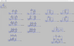
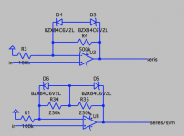
If anyone is interested, here are some basic circuits I ended up with using mostly the same diodes on all the circuits --as to keep the experiment consistent and changing the values would only change the clipping threshold-- and trying to keep the resistance in the feedback loop at 500K to keep the gain constant --where there are two resistors in the loop you can change the values to be..say 100k and 400k this will ensure you have the same gain but might change the symmetry--.
LTSpice file:
Spice
I was surprised to see what wide range of reactions you can get like different levels of compression, how the compression releases over time and signal input, and how you can change the symmetry.
If anyone else has creative techniques to saturate their signal, feel free to share.
Attachments
..how the compression releases over time and signal input...
I'm interested, what do you mean by this? Without any sort of RC or LC components involved shouldn't effects to gain ("compression") be instantenous?
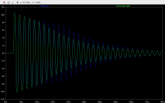
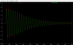
It's kind of more an input level or threshold thing. in this case, the threshold should be around 6.2V where V(series/sym) ducks below that threshold at about 19ms and it starts compressing much less where V(series) compresses the signal to about 30ms and then starts compressing less.
If I want to be accurate what would I call this reaction if not a "release"? Because we are talking about the poit where the gain of the opamp is low enough not to be compressed by the diodes.
If I want to be accurate what would I call this reaction if not a "release"? Because we are talking about the poit where the gain of the opamp is low enough not to be compressed by the diodes.
Attachments
Not sure how you achieved those results; as Teemuk said clipping with diodes, Zener ones in this case, is an instantaneous effect.
And they clip at a fixed voltage, in your example it would be Vz + 1 diode drop (about 600-700mV) so some 6.8V peak, not sure how could they exhibit that "peak voltage decreasing with time" along an 84 ms period.
And they clip at a fixed voltage, in your example it would be Vz + 1 diode drop (about 600-700mV) so some 6.8V peak, not sure how could they exhibit that "peak voltage decreasing with time" along an 84 ms period.
Better to clip prior to the amplifying stage, unless you use very low impedance feedback elements (when diode leakage becomes much less significant). Diode leakage in the feedback network will cause high distortion in the pass band.
There are op amp circuits that mimic the ideal diode but that gets a bit complex.
Simple buffer attached. Adjust the supply rails to the desired clip level.
There are op amp circuits that mimic the ideal diode but that gets a bit complex.
Simple buffer attached. Adjust the supply rails to the desired clip level.
Attachments
Presuming you're not trying to build Yet Another Tubescreamer or Big Muff variant then there's a pile of prior art you should be looking at E.g. the Fetzer, e.g. half of RunOffGroove's circuits.
There's also things like the Thunderbird which are diode based (with very clever shifting operating points).
Thanks to Gnobuddy for highlighting the work of Tiago Azevedo on convincing a twin-BJT stage to have triode like clipping.
And you should really read through Gnobuddy's Tube Emulation thread.
Also the limiter stage in Fred Nachbaur's Dogzilla is worth studying.

And nothing new is really new
There's also things like the Thunderbird which are diode based (with very clever shifting operating points).
Thanks to Gnobuddy for highlighting the work of Tiago Azevedo on convincing a twin-BJT stage to have triode like clipping.
And you should really read through Gnobuddy's Tube Emulation thread.
Also the limiter stage in Fred Nachbaur's Dogzilla is worth studying.
And nothing new is really new
...old (60´s era) VOX power amp limiter stage, they avoided SS clipping like the plague, so they added this adjustable limiter ....

This is a very old soft limiter circuit from the 1980's to emulate valve type distortion.
Its a bit more subtle than the usual fuzz box circuit....

Last edited:
Not sure how you achieved those results; as Teemuk said clipping with diodes, Zener ones in this case, is an instantaneous effect.
And they clip at a fixed voltage, in your example it would be Vz + 1 diode drop (about 600-700mV) so some 6.8V peak, not sure how could they exhibit that "peak voltage decreasing with time" along an 84 ms period.
I can see how that can be confusing, and I agree that "release over time" might not have been the most accurate way to describe it. A come accurate way to explain this is to talk about the clipping threshold.
In some orientations, the diodes ( I assume ) are causing the opamp to considerably increase its gain, but the diodes are clamping that signal down ( at a voltage set by the value of the diodes ) without hard clipping (compressing the signal to some extent). In some cases where the gain of the opamp is extremely high most of the signal is amplified above the threshold resulting in a great deal of sustain.

Here is another example you can see V(h3) is a lot more compressed than V(h2) especially when it comes to the "attack" or higher voltages of the signal but there is a point where they "blend" together and react the same.

Keeping V(h3) as a reference here we can see that they have the same clipping threshold and are almost identical when it comes to larger signals, but V(series) drops below the threshold much sooner ( hence me referring to it as a release). this is probably because the gain of V(series) is a bit lower.

I hope that clears things up a little bit? I wanted to breadboard these circuits to listed how they differ sonically but everything is in boxes because we are moving soon. Se experimenting in LTSpice is just a way to keep my head busy for now.
Better to clip prior to the amplifying stage, unless you use very low impedance feedback elements (when diode leakage becomes much less significant). Diode leakage in the feedback network will cause high distortion in the pass band.
There are op amp circuits that mimic the ideal diode but that gets a bit complex.
Simple buffer attached. Adjust the supply rails to the desired clip level.
Johno, I think in this application high distortion is desirable, but I have not tried putting clipping diodes in my supply rails. I see it can cause quite hard clipping. You can also achieve hard clipping by inserting those diodes between the output and ground.
Presuming you're not trying to build Yet Another Tubescreamer or Big Muff variant then there's a pile of prior art you should be looking at E.g. the Fetzer, e.g. half of RunOffGroove's circuits <snip>
Thanks thoglette! I have read the Runoffgroove articles a couple of times ( and I will probably go through them a couple of times more ).
These are all very interesting threads, I am exited to try them out on the breadboard.
Thanks!
Edit: I see the Images are too small I will try and attach them in the same order as above.
Last edited by a moderator:
Oh, I forgot a few more links from Printer2
And there's SSB's Distortion by Amplification Thread which, I confess, I've not even attempted to make head or tail of.
The Fet circuit is the work of a Russian fellow (KMG) that took ideas from others and tweaked it till the waveforms matched an actual 12AX7. Our mjd_tech spent some time with the circuit and said KMG seemed to have got it right.
Tube Emulation & EQ
Fet version of the JCM800 using LND150 mosfets
Main page
And there's SSB's Distortion by Amplification Thread which, I confess, I've not even attempted to make head or tail of.
I glanced at it. In his long write-up, he (SSB) suggests that converting the guitar signal into a rigid, unvarying square wave with a comparator is the best possible distortion sound. And then he seems to be rather excited that you can do this with discrete transistors, rather than using an op-amp.And there's SSB's Distortion by Amplification Thread which, I confess, I've not even attempted to make head or tail of.
To me it sounds as though SSB has (inadvertently?) journeyed right back to the first nasty-sounding and inexpressive transistor fuzz circuits from the early 1960s. Possibly without being aware that he's repeating history that's nearly 60 years old now - a little Internet digging turns up the fact that an American guitarist named Al Casey used an early fuzz-box on his 1960 song "Go On Home". (The fuzz-box was supposedly custom made by a local tech for the recording studio owner.)
I will confess that I don't quite understand the point of the exercise. Most guitarists have been glad to get away from those early buzzy, inexpressive circuits, and move on to subtler distortion and overdrive circuits that preserve at least some trace of the guitar's dynamics and timbre. By 1969, the first Big Muff Pi was already demonstrating the musical advantages of a softer and more musical distortion.
-Gnobuddy
Below is what I've used recently in a very soft clipping stage that is able to keep the waveforms and dynamics pretty much intact.
Shown is a 200Hz fundamental with a 1300Hz signal on top. Input amplitude is doubled for each trace. One can add a soft slew-rate limiter at the ouput so as to avoid too much high frequency signals at high level. With this, it never sounds like clipping at all, the tone just gets thicker and has more sustain as gain is increased but it never gets nasty (well, complex chords will have their share of intermodulation distortion which often sounds " broken" -- but that's a part of the classic distorted electric guitar tone anyway). Without the slew limiter a bit less benign at high frequencies, but still very usable.
Shown is a 200Hz fundamental with a 1300Hz signal on top. Input amplitude is doubled for each trace. One can add a soft slew-rate limiter at the ouput so as to avoid too much high frequency signals at high level. With this, it never sounds like clipping at all, the tone just gets thicker and has more sustain as gain is increased but it never gets nasty (well, complex chords will have their share of intermodulation distortion which often sounds " broken" -- but that's a part of the classic distorted electric guitar tone anyway). Without the slew limiter a bit less benign at high frequencies, but still very usable.
Attachments
That looks interesting, thanks for sharing. I'm definitely throwing that together on a breadboard to see what it sounds like.Below is what I've used recently in a very soft clipping stage that is able to keep the waveforms and dynamics pretty much intact.
Might I ask what corner frequency you're using for the lowpass filter / slew-rate limiter?One can add a soft slew-rate limiter at the ouput so as to avoid too much high frequency signals at high level. With this, it never sounds like clipping at all
Thanks!
-Gnobuddy
there is a pretty large database with schematics derived from commercial pedals:
Guitar FX Layouts
i've built 1 or 2 of them but had trouble with complexity and debugging. otherwise they kind of worked.
Guitar FX Layouts
i've built 1 or 2 of them but had trouble with complexity and debugging. otherwise they kind of worked.
Below is what I've used recently in a very soft clipping stage that is able to keep the waveforms and dynamics pretty much intact. <snip>
KSTR, this looks very interesting. I can't wait to get it on a breadboard and hear what it sounds like. How did you come up with it?
The circuit is derived from a HiFi-Softclipper I had designed. In contrary to a guitar softclipper, a HiFi clipper needs to max out a certain voltage and must never exceed that no matter how hard it is driven, as it's purpose is to keep the amplifier from hard clipping.
The curvature we get from the clipper is not too different from a regular diode clipper (series resistor feeding two antiparallel regular silicon diodes), just the increase in max voltage for each doubling of input voltage is larger, giving a more rounded curvature and less "compression". And of course it has intrinsic gain and much higher output voltage.
Below the slew-rate limiter is included in the circuit. At low drive, it's a lowpass (-3dB @ 8kHz) formed by the JFET resistance but at higher edge rate the JFET can't deliver the full current into the capacitor because the current start slimiting and won't get any higher which charges the capacitor at fixed rate. A low Idss JFET (<1mA) is required like the 2N4119/MMBF4119.
For comparison, the effect of a simple lowpass with the same corner frequency is shown. The plot shows a set of frequencies at full gain (10V input), nornalized to periods for ease of comparison, those are (green to magenta) 100Hz, 300Hz, 1kHz, 3kHz, 10kHz.
We can see the edge rate of the higher frequencies is strongly reduced as is the amplitude, the max edge rate of the slew limiter is only one third of the lowpass. The 10kHz trace is triangular which means only 10% or so of distortion whereas the lowpass output has much more harmonics.
At low drive, the curves for lowpass and limiter output are indentical (not shown).
Wrt to parts choice, you need a beefy opamp for the gain cell as well as the stage that drives the clipper as it must be able to drive 10mA output current easily to 10V (TL07x need not apply, 5532 much better, I used OPA1688 on DIL adapter -- excellent FET-input OpAmp with low distortion, rail-to-rail output and lot's of output current. The output of the limiter also must be buffered, a TL07x will do here. The load capacitor for the clipper needs individual tweaking because JFETs have huge tolerances but.
Btw, the two 10k resistors in the clipper are optional, the help to flatten the waveform tops at very high output levels to keep the opamp from clipping. If they are made lower value, the tops actually start to "fold over" and develop dips in the middle, this may be useful to increase the hamonic content at high drive. Also the clipper's excact operating point is somehwat temperature dependant like in any typical diode-based clipper.
I still have only breadboarded this and need to tweak and test more parts for usability etc, end goal would be a PCB with all the bells and jingles required to build that thing porperly into a standard stomp box format (using 9V single supply, even when from an AC adpater with more current capability than batteries, is going to be a challenge). Personally, I might not have too much use for it as I'm fully happy with sound and capabilites of my tube amps (like Marshall JCM800 2203, with some tweaks).
Attachments
Last edited:
So a regular diode circuit will do the same but will be limited in output voltage, more or less?The curvature we get from the clipper is not too different from a regular diode clipper (series resistor feeding two antiparallel regular silicon diodes), just the increase in max voltage for each doubling of input voltage is larger, giving a more rounded curvature and less "compression". And of course it has intrinsic gain and much higher output voltage.
Not quite. The gross shape is similar but the standard diode clipper curves are not as round and not so nicely staggered.
See plots below. The first shows the response to a sine wave with increasing level whereas the second plot showns the transfer function (output voltage vs. input voltage, note the log scale on the input voltage). It is apparant that the complex circuit has a better response, the "gain" vs input voltage has a much smoother and notably monotonic shape. It compresses the waveform more at lower gains and less at higher gains.
See plots below. The first shows the response to a sine wave with increasing level whereas the second plot showns the transfer function (output voltage vs. input voltage, note the log scale on the input voltage). It is apparant that the complex circuit has a better response, the "gain" vs input voltage has a much smoother and notably monotonic shape. It compresses the waveform more at lower gains and less at higher gains.
Attachments
Another way to look at it is the momentary gain vs input voltage. The diode clipper remains at 30x until 100mV then starts to drop rapidly with a sharp transition while the complex circuit has a very gradual decrease of gain.
The circuit is also ideal for feeding an even order distortion stage because that's typically what we want as well for our guitar signal to sound more open. Normally such a stage has a very limited range where it is really effective and nice sounding, at low gains it doesn't do much while at higher gain it will clip readily on the expanding slope. Too much 2nd order distortion doesn't sound too well to my ears, sort of half-wave rectified.
The circuit is also ideal for feeding an even order distortion stage because that's typically what we want as well for our guitar signal to sound more open. Normally such a stage has a very limited range where it is really effective and nice sounding, at low gains it doesn't do much while at higher gain it will clip readily on the expanding slope. Too much 2nd order distortion doesn't sound too well to my ears, sort of half-wave rectified.
Attachments
- Status
- This old topic is closed. If you want to reopen this topic, contact a moderator using the "Report Post" button.
- Home
- Live Sound
- Instruments and Amps
- show your creative clipping circuits