Hi everyone,
I used to own an MXR Bass DI+ and it was super convenient because I didn't have to lug a bass amp around where ever I went and the pedal was phantom powered.
I am trying to build a new bass pedal starting with the balanced out. I successfully split the P48 into a dual rail supply for my opamps and signal is passing right until R9 and R10 at which point it disappears. I assume I am sending via R11 and R12 through ph and down to ground, but this is taken pretty much exactly from a schematic I found on
ESP - Direct Injection Box for Recording and PA Systems
Does anyone have any advice on how to separate my signal and power in this application, and can phantom power provide me with enough current for the rest of my design? ( it must be possible if MXR and Tech21 SansAmp can do it. )
An externally hosted image should be here but it was not working when we last tested it.
Last edited:
 Relocated to instruments and amps from solid state.
I tried to link my schematic, here are some new attachments I have made some changes from the first design.
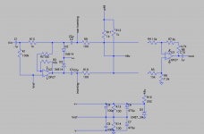
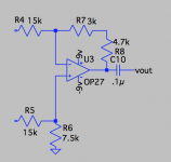
So the whole thing is just a push-pull design sending the same signal through pins 2 and 3 but one out of phase with the other That is what drives the differential amplifier on the mixer side.
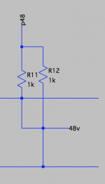
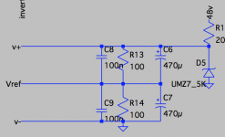
Most mixers ( and preamps ) has pins 2 and 3 connected to 48v via 6k8 resistors, p48 is labeled as that source I am bringing them both together as the 48v source. Then I am using a diode rectifier to bring the 48v to just below 8v and splitting that into a +4v and -4v source for the opamp.
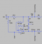
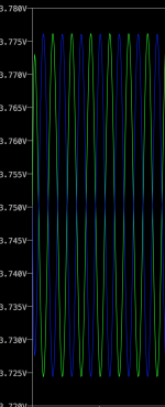
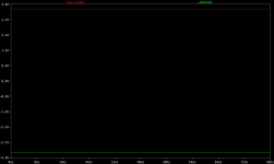
my input is split into two signals one non-inverted signal and one inverted signal. I attached an image that shows these two signals at the same amplitude but out of phase tapped between C2//R9 and C3//R10 showing that my inverting opamp is doing its job, but once you go past R9 and 10 the signal dies. I need to separate it from the 48v and I am unsure about how to do that.
I hope I explained this clearly.
So the whole thing is just a push-pull design sending the same signal through pins 2 and 3 but one out of phase with the other That is what drives the differential amplifier on the mixer side.
Most mixers ( and preamps ) has pins 2 and 3 connected to 48v via 6k8 resistors, p48 is labeled as that source I am bringing them both together as the 48v source. Then I am using a diode rectifier to bring the 48v to just below 8v and splitting that into a +4v and -4v source for the opamp.
my input is split into two signals one non-inverted signal and one inverted signal. I attached an image that shows these two signals at the same amplitude but out of phase tapped between C2//R9 and C3//R10 showing that my inverting opamp is doing its job, but once you go past R9 and 10 the signal dies. I need to separate it from the 48v and I am unsure about how to do that.
I hope I explained this clearly.
Attachments
The plain 48V take off ( not p48 ) creates a short circuit across R9 and R10.
Thanks, epicyclic. I made some changes to my Schem. I wired the Phantom power from the mixer correctly, That solved my signal problem, I am now getting a perfect 1:1 signal on the other side of the differential amp of my "mixer".
The circuit as you have drawn it will give a very poorly balanced (balanced) output as you are not buffering the non inverting output
You are 100% correct so I put the original opamp back. Although my Zin and Zout are still pretty much the same when I measure them. But that might be because of my simulated "mixer" not having the same Zin my actual preamp would, and I don't have any HighZ output from say a gain stage (or any preamp circuit), But I plan on starting that design once I am confident that I have a working balanced out and I can use the Phantom Power to power the rest of my design.
Could you maybe show EVERTHING you built and how it all interconnects? Where is the bipolar 9V supply coming from?
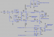
Hi leadbelly, I attached my full circuit with some comments.
I have a 48v power source going through two 6k8 resistors to Pin 2 and 3 (This would be similar to how any preamp/mixer console would send Phantom Power)
The Differential amp on the far right is supposed to emulate a Balance In from a preamp.
Then on my Balanced Out side Of things, I am taking the 48V from pins 2 and 3 through 1k resistors (witch still Gives me 48V) then I am regulating it using a diode down to about 9V. The 9V is devided to 4.5V witch is my Bias for the opamps ( or Vref and +4.5V and -4.5V on the opamps ).
Attachments
- Status
- This old topic is closed. If you want to reopen this topic, contact a moderator using the "Report Post" button.
- Home
- Live Sound
- Instruments and Amps
- phantom power in bass pedal