Hi group,
ive recently repaired a fender bassman 10 which turned out to be a faulty phase inverter valve. The amp now sound and runs ok.
On checking its output into a dummy 8 ohm load, the max power I can get from the output is around 25 to 30 watts RMS. This was confirmed on a multimeter and a scope @400 hz 110mV input as per fender instructions. The amp is rated as the 70w rms type as highlighted on the rear of the amp.
The entire amp has been checked and all voltages are in spec. Iam suspecting low valve emission. Boosting the heater to find out made no difference. From the grid input to the anode appears to give just a gain of 8 before it clips.
My question is has anyone experienced this from low output valves before I lash out on a new set.
Any advice would be appreciated
Supplying a schematic and a set of voltages would help.Any advice would be appreciated
My current 6L6 (ok, 807) amp is designed to only produce 8W.
") (OK, so most of Leo's Bassmen were PP6L6 and should make 50W. Which one?)
(OK, so most of Leo's Bassmen were PP6L6 and should make 50W. Which one?)But a gain of eight is just wrong. What are the gains for each of the individual stages?
I'd be suspecting a mechanical fault (dry joint, bad connector, broken resistor or similar) long before low emission.
Last edited:
Depends on which one and what the wall voltage is on any given day - Rob Robinette quotes 432V on the 5F6A in his analysis of the classic bassmanThat amp has about 475 volts on the output plates doesn't it?
There's a really big PDF on the 5F6A with lots of other info sort'a hidden on Robs site here
Ah, I'm also presuming you've checked that the screen resistors haven't died?
Last edited:
thanks all for your responses, I have 450v on the centre tap of the output transformer and 225v on each plate at idle. I put a 2.2 ohm resistor between each cathode just to monitor the current delivered in each valve. Idle they sat at around 35mA and just before it clipped on full output around 80mA. @ 225v gave around 18watt x 2 = approx. 36 watt total which appeared to be close to my output rms voltage squared into 8 ohm.
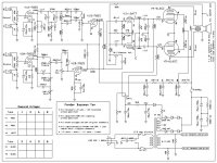
It does look like soft emisions. I've attached a schematic for reference. All the voltages are ok apart from I found the point between the 330k grid leak resistors on the 12AT7 phase inverter was low at about 110v instead of 132v.
Thanks again
John
It does look like soft emisions. I've attached a schematic for reference. All the voltages are ok apart from I found the point between the 330k grid leak resistors on the 12AT7 phase inverter was low at about 110v instead of 132v.
Thanks again
John
Attachments
Hi Chris and parafeed, apologies, by now you've probably realised ive boobed with my figures. I was quoting from the schematic which I had made notes on and for some reason posted them incorrect. i wasn't in front of the amp at the time. I did realise my mistake and I knew what the replies would be. Just one of those days.
That aside, ive done some readings direct from the amp and to be honest it appears to be ok from the valve side of things.
I have 485v on both plates, i commoned together the cathodes and measured the idle current at 39.3mA.
I then applied an input and increased it to its maximum just over 110mv which was just below the point where the output signal started to clip, the current then read 128ma. it would appear 485 x 0.128 = 62 watts rms driven through the output. This i would expect to be ok.
Where the confusion lies is the actual output across the transformer into 8 ohm only gives around 15v rms just before clipping. 15v squared / 8 =28 watts. I understand the load isn't a true impedance like the speaker, have i overlooked something in this case? even with transformer losses its a lot to appear to go missing.
....485 x 0.128 = 62 watts rms driven through the output....
DC power _TO_ the final is _NOT_ sine power Out of the final.
(And being that your 62 Watts is DC, the "rms" is not necessary, and promotes confusion.)
Clean sine class B is at-best 78% efficient. Real-world pentode amps run 50%-60%.
62 Watts DC is likely 35W clean sine audio output power. This is in-sight of your observed 28W; but 45% efficiency is lowish for a hot-rod power stage driven TO the edge of clipping.
How much does the B+ drop from idle to full power? Even 10% sag makes your numbers agree with each other better.
However the Bassman 10 is a hot-rodded 5F6a final stage (preamp different). With the crystal rectifiers and all, power rose from ~~40W to over 50W. So you are shy of where you should be.
You are half-power. Are you sure of your dummy-load? Are you sure of the amp tap? BM10 is supposed to be 8 Ohm only, but if someone has tucked a 5F6a OT (4r) in there your numbers make more sense.
I do not understand why you have not *already* tried different tubes. That was always the first step in diagnosing lame guitar amps. We often did not know what the B+ or Rl was, but if new tubes "fixed it" then job done, no brain-pain. Old tubes sometimes last forever and new tubes sometimes crap-out fast, so don't even wonder "IF" you should replace them. They are socketed for a reason.
Last edited:
Hi PRR
thanks for the informative info, my B+ sags from 485 to 470v on full power just before clipping. All the amp looks original and is fitted with a marked fender o/p transformer. Iam not familiar with the numbers but top line shows 013897, bottom shows EIA606-921 if that resembles anything.
I think ill get a spare set of 6L6GC and compare them out of curiosity and see what the results are as I don't have a valve tester.
many thanks
Hi John,
That was suggested earlier, but now there is another wrinkle. Many 6L6GC tubes will not put up with a Fender amplifier. I found two tubes (aside from good NOS tubes) that will last. One is a 7581A (which is a 35 W 6L6GC) and the Electroharmonix 6L6EH. All the others I tried suffered from hum or excessive dissipation (red plates). So you have to buy tubes that will take the higher B+. I'd have to say that the others I tried were probably sub-standard in a normal 6L6GC application as well as just plain bad for Fenders.
When I measured the 6L6GC plate and compared it to the 7581A tubes I had, they were the same size as far as I could tell. The other 6L6GC had smaller plate structures. That might be the reason the 6L6EH worked so well.
-Chris
Gents, there is some funky information going around. There are a couple of different models of the Bassman Ten. There are: The Bassman Ten amp The Bassman Ten 70-Watt
John O: Where did you get that schematic, it's source please.
Most of the stuff from the era of the amp you have aren't the same as Leo Fender's original amps. Master volume amp's are noted for issues. Not putting you or anyone down it just is what it is. Naturally the doumentation isn't that good either.
The Bassman amps from 6G6 through the Bassman AA371 are all 4 ohm amps. (the output). Typically you can go up or down one value...8 ohms ok, 2 ohms can be kinda tricky....
The OP original schematic is what is needed. Or the OP needs to take and post pics of the following: Amp's front panel. Back panel. Tube chart. Chassis Wiring. Tube socket (where tubes hang down) and The Dog House (the place where the main caps are located on the tube socket side of the board (hang down).
To the OP, I would change and ensure you have the 125P5D power tranny 2k2 Choke Those number should be stamped similar to the output tranny. Later Bassman amp might have 018343 output tranny, it also is 4 ohm 40 watts. The Bassman Ten 70Watt amp had the full wave bridge.
Those amps have a lot of needless caps in them... well they used to be needless because tube power was dying back then and the amps were not wired as well as in the 50's and 60's the MFG needed fixes.
Those 7581As are some awesome sounding tubes. The Sylvania's many MI Techs feel they are one of the best 6L6s series tubes ever made...surpassing even the vaunted RCA 6L6GC black plate.
Running a pair of 7581A and EL34 in the MesaBoogie MKII++, it just doesn't get much better than that.
If anyone has a pair of the WE350B consider a trade for NOS Quad+ of 7581As, that getting up there in the price (7581As).
I can't recall if that Bassman 10 in the tall Box, similar to the Bandmaster... some of the early Bassman heads can't take the taller 7581A... they need the 6L6GC or the small bottle 5881 which also sound great.
Cheers,
Sorry for the brain dump, hope you don't mind. PM me if got questions I don't always look over here.
Last edited:
5881 (USA made) = 6L6WGB = 'ruggedized' 6L6GB
6L6WGB data sheet: https://frank.pocnet.net/sheets/087/6/6L6WGB.pdf
6L6GB data sheet: https://frank.pocnet.net/sheets/127/6/6L6GB.pdf
Ratings for 6L6GB and 6L6WGB look to be identical.
max plate dissipation = 22 W
max plate voltage = 400V
max screen dissipation = 2.8 W
max screen voltage = 300V
________________________________
5881 (Sovtek) = 6P3C-E, which is different from 6L6 types, but can be used as a substitute if bias is adjusted accordingly. It appears that the 6P3C-E is capable of plate dissipation around 30 watts without unduly short service life.
Sovtek 6L6GC is misnamed. It is a 6P3C (no "-E") that is rated something like an old 6L6G or 6L6GA (Vp max = 360V, Vg2 max = 270V, Pdiss max = 19W, g2 diss max = 2.5W).
6L6G data: https://frank.pocnet.net/sheets/137/6/6L6G.pdf
________________________________
6L6GC (USA made) = 7581A (USA made)
6L6GC (USA) tube data: https://frank.pocnet.net/sheets/093/6/6L6GC.pdf
max plate dissipation = 30 W
max plate voltage = 500V
max screen dissipation = 5 W
max screen voltage = 450V (or 500V if used with UL OPT)
________________________________
They're all supposed to have the same electrical characteristics (transconductance, internal resistances and capacitances, etc.), and they all have the same octal base and pinout, but they differ in maximum voltage and dissipation limits.
Right?
--
70W (without clipping) is impossible/fantasy (pick one).
50W is realistic, and that with fresh tubes, so 28/30W with well worn tubes is very possible.
I have personally measured Silverface Twin Reverb putting out 40W ... with good but 20 y.o. 6L6, and Marshall JCM800 with similar age EL34 putting out just 50W RMS, again before visibly clipping, 4 bottles in each case.
Fresh tubes restored "almost" 100W RMS (which is VERY loud) on both.
Only "4 bottle" amps which easily surpass real 100W RMS are American Marshall which use 6550 and V series Ampeg which use 7027, both "stronger than 6L6/EL34" and with scary high 530/560V +V.
But with standard tubes and 436/460V +V you simply don´t have that much power available.
Hi rongon,
Not right. Look in more places for your specs. The 7581A is a 35 watt device that retains the characteristic curves of the 6L6GC. 7581A sort of equals a KT66. I don't know about the 6L6GA and GB because I haven't used them. The 6L6 is a 19 watt device in a metal envelope.
-Chris
Not right. Look in more places for your specs. The 7581A is a 35 watt device that retains the characteristic curves of the 6L6GC. 7581A sort of equals a KT66. I don't know about the 6L6GA and GB because I haven't used them. The 6L6 is a 19 watt device in a metal envelope.
-Chris
I don't know about the 6L6GA and GB because I haven't used them. The 6L6 is a 19 watt device in a metal envelope.
The 6L6 (metal envelope), 6L6G, 6L6GA and 6L6GB all have the same internal guts, which are also shared with 6BD5's and most 807's, 1625's and 6BG6's. The only differences are the bottles, bases and pinouts.
They have 19 watt plates according to the "design center" rating system. This represents the center of the bell curve for all possible operating conditions for apparatus using a given tube. Some data sheets use the "design maximum" rating system which is the worse case operating conditions for a given apparatus. The design maximum ratings are usually about 10% higher. The 6BD5 has a lower dissipation rating due to the tiny bottle and it's TV sweep use.
The 6L6GC got a plate with larger fins, grid support fins, and "improved metallurgy" increasing its dissipation ratings. Most 6L6GC data sheets also used the design maximum rating system making the increase look larger than it actually was.
The 6L6WGB is the internals of the 6L6GC with a rectangular box plate stuffed into a short bottle, originally for a military application. I have a dozen or so of these that came from military scrap, all well used. Some also carry 6L6WGB / 5881 designations. The bases of these are all quite discolored from heat, but they all work.
I stuffed 4 of them in a Chinese "100 Watt" amp head chassis that I got used without tubes on Ebay. It runs about 465 volts with a 5U4 in the 5AR4 socket. The amp works and is deafeningly loud, but I haven't measured the power yet. There are no glowing tubes in a dark room, but this is a very unscientific test since I haven't even measured the bias. I unboxed the bare chassis, stuffed 12 randomly selected tubes in it from my junk box and cranked it up!
Hi George,
You're a trusting fella!
When working on a Fender or anything close to maximum ratings for a tube, I always perform the dark room test. I don't care what the instruments tell me, I want the tube to talk to me. They opt out all by themselves. New tubes in a Fender Twin or similar always has me on edge. Only a few new tubes will take that setup. It used to be that any good branded new tube could handle a Twin, but not any more. The NOS tubes should be fine, but they often sell for silly amounts of money.
-Chris
I always fit matched pairs of 6n3c-e Ukraine manufactured 6L6GC valves.
You will never ever get a problem with them. They are similar to 5881 but for the Military, so rugged.
Always check the anode current at idle and set as per the list below for each valve. Check the HT on the screen grids.
Anode voltages ;
6L6GC - 30W Hot (70%) Avg (60%) Cool (50%)
300V 70mA 60mA 50mA 325V 65mA 55mA 46mA 350V 60mA 51mA 43mA 375V 56mA 48mA 40mA 400V 53mA 45mA 38mA 425V 49mA 42mA 35mA 450V 47mA 40mA 33mA 475V 44mA 38mA 32mA 500V 42mA 36mA 30mA
Last edited:
- Status
- This old topic is closed. If you want to reopen this topic, contact a moderator using the "Report Post" button.