I am using the schematic from a Gallien Kruger bass amp to make a preamp for an amp I'm building. I'm just using the 2nd and 3rd valves with midrange treble and bass controls. My question is about the cathode bypass on the second 12ax7 , which has a 0.22uf capacitor in series with a 150R resistor bypassing a 1.5k resistor. All the other triodes have standard 1.5K bypassed with 22uf capacitors.
I think that the resistor in series is there to maximise the gain , but don't inderstand why the cap is so small , especially in a bass amp where you would imagine you want to use high value caps. I realise that the resistor being there changes the value of cap needed , but from searching the web for other instances and explanations I have only found reference to using slightly lower value caps , say 15uf.
Can anyone cast a light on this?
I think I probably need a tube emulation program to work it out for myself , any recommendations for software preferably mac?
Attachments
In this case it is used as a "treble enhancer"; at high frequency the cap tends to be byapssed (its impedance going lower) so the resistor of 150 is in (almost) parallel with 1k5 and the gain increase
Maybe because the impedance of the previous stage is very high so in the conjunction with Miller caps the freq. resp. became limited.
It is like a freq. compensation
Walter
Maybe because the impedance of the previous stage is very high so in the conjunction with Miller caps the freq. resp. became limited.
It is like a freq. compensation
Walter
Last edited:
Cathode bypass
I suppose that what I don't quite get is that the lower value cap is reducing the amount of bass frequencies available to all the subsequent preamp triodes , so the overall frequency range of the amp is limited regardless of the way the other triodes are configured or the size of their bypass caps. Which seems odd for a bass amp , you'd think you would want the fullest range possible available to then be adjusted by the tone control filters.
I suppose that what I don't quite get is that the lower value cap is reducing the amount of bass frequencies available to all the subsequent preamp triodes , so the overall frequency range of the amp is limited regardless of the way the other triodes are configured or the size of their bypass caps. Which seems odd for a bass amp , you'd think you would want the fullest range possible available to then be adjusted by the tone control filters.
...preamp for an amp I'm building.
...I think I probably need a tube emulation program to work it out...
What would Leo Fender do? Whip-out a mouse and iBook? No, if he had mice in Fullerton he got poison bait.
If you are really building it, I'd think it would be far easier to tack it and try. Alligator clips are your friends.
Attachments
Remember, a bypassed cathode resistor of a half-12AX7 does not create a typical high-pass filter response (with bass rolled off more and more as you go lower and lower down in frequency).I suppose that what I don't quite get is that the lower value cap is reducing the amount of bass frequencies available to all the subsequent preamp triodes
Rather, what is created is a shelving filter, with two wide flat gain regions, and a small rise of a few dB between those two plateaus.
Using a very small cap (like your example) moves that small rise to a higher frequency, so that frequencies above a certain point are boosted a little. It does not roll off deep bass frequencies.
I realized a while ago that there is a great deal of confusion and mis-information out there about cathode bypass cap sizing, particularly when it comes to the ubiquitous 12AX7 triodes. The confusion extended to myself, as I realized I could not trust the numbers I saw elsewhere, and didn't know how to work them out for myself (it's harder for triodes than for pentodes or transistors or FETs.)
I've also seen very odd results from simulating 12AX7s in LTSpice, so I don't trust the 12AX7 Spice models out there.
Seeing no good alternative, I recently sat down and worked out the mathematics myself, and then used my results to write a little computer program to calculate the frequency response of a triode with a bypassed cathode resistor.
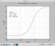
When I put in a 1.5k cathode resistor, half a 12AX7, and a 0.22uF cathode bypass cap, the frequency response is flat below about 100 Hz, and also flat above about 3 kHz. Between those two flat regions there is about a 5 dB rise, with the +3dB point at about 800 Hz. (See attached image.)
My program doesn't include the 150 ohm series resistor you mentioned, but I believe it will not have much effect on the outcome (based on my understanding of the impedances it is working into.) It will slightly lower the height difference between the two plateaus in the frequency response, but not by much.
My program also does not include the effect of coupling capacitors to preceding or subsequent stages. (If those are too small, they really will roll off deep bass.) We're looking only at the effect of the cathode bypass cap here.
Note that the frequency response shown in is flat all the way down to DC - even the tiny 0.22uF cap does not cause deep bass to roll off! Instead, as Walter said, it only boosts treble a little bit. (5 dB is not a huge boost, keep in mind the y-axis scale in my graph is zoomed in quite a bit.)
-Gnobuddy
Attachments
- Status
- This old topic is closed. If you want to reopen this topic, contact a moderator using the "Report Post" button.
- Home
- Live Sound
- Instruments and Amps
- Cathode bypass 12ax7