I was just given half of a Stroboconn 6T mechanical instrument tuner.
The tuning unit half...the scanning unit with the motorized strobe discs is missing. I haven’t looked closely enough yet to tell if the transformers have any ID #’s.
Found a manual online...
The Conn p/n for the tuning unit OPT is 56187.
It has a CT primary driven by parallel PO 6V6’s.
The secondary drives coils on a mechanically tunable tuning fork transducer...if it’s like reverb tank technology...could be any impedance...whatever they needed.
Long shot question of the day:
Anyone know anything about this output transformer?
(Other than it being black and having steel & copper inside).
Thanks
Murray
I found a 1951 Radio-Electronics full text in archive.org that gives extensive tech. info on how it works, but nothing about the transformer.
I explained incorrectly above. Tuning fork is driven somehow by a regenerative oscillator PA with a pair of PP 6V6’s & output transformer. The extremely stable tuning fork oscillator then is amplified in the half I have with the PPP 6V6 quad. This power oscillator drives the motor that rotates 12 geared strobe discs and maybe the neon lamp that illuminates the discs. They run at different speeds in ratios as close to 2^(1/12) as can be done with gear tooth ratios. Each disc has multiple rings for higher octaves.
I have the Peterson Strobotuner app on my phone, the explanation of the mechanical version helps me understand what I haven’t gotten from the Peterson instrux (apparently I need more info to be less confused).
Only mention so far about motor on OPT secondary is the process of using a 500 ohm dummy load when the motor is not being driven.
That doesn't assure the motor is equivalent to a 500 ohm load but raises that potentially disappointing possibility...the OPT would not be suitable to drive a conventional loudspeaker if that’s the case.
Last edited:
For anyone interested:
Full text of "Radio Electronics 1948-1992"
July 1951; search for Conn. There are 11 occurrences in there.
This link has 2 or 3 different vintage manuals, some with schematics.
Stroboconn
Full text of "Radio Electronics 1948-1992"
July 1951; search for Conn. There are 11 occurrences in there.
This link has 2 or 3 different vintage manuals, some with schematics.
Stroboconn
Last edited:
Ha - finding everything else...
https://patentimages.storage.googleapis.com/d2/a8/ad/2932447d52d5a1/US2286030.pdf
https://patentimages.storage.googleapis.com/d2/a8/ad/2932447d52d5a1/US2286030.pdf
...That doesn't assure the motor is equivalent to a 500 ohm load....
Your later post has the info:
"The motor was made by Bodine Electric Company, Chicago. (It's rated at 110 V, 55 Hz. 0.26 A, 1/120 HP. 1-phase, continuous duty, 1650 RPM. Capacitor 3.75 [µF?], 40 °C temperature rise, No. 7270733, Type NYC-12.)"
110V 0.26A is 423 Ohms 28.6 Watts. (So you see why two 14W pairs of 6V6.)
Note also that the amp ran "ONLY" 55 cycles (Hz). There's a trim with fork weights but this will be slim. So far you only can expect say 50-60Hz frequency response. In fact you can't wind an untuned transformer that narrow, but such iron will sometimes cut-off by 500Hz. (And unlikely to go far below 50Hz because it was already heavy/costly.)
The only thing really comes to mind IS a motor. There is sometimes need to drive small sync motors away from 60Hz. Such as turntables for "78"s which were often not cut at 78. Or the home-cut disks I got with a portable disk-cutter, some recorded on bad power. Build a small 30Hz-200Hz oscillator and let the Conn amp drive the turntable motor. However for many years it has been so much simpler to transcribe at whatever speed and re-speed it digitally.
I still have several Conn 6T5 12-wheel tuners. One working even.
The neon is simply driven by the mic circuit. It flashes at whatever frequency you feed the thing. The wheels all spin at a steady rate, their motor driven by the power oscillator.
The fork system is extremely stable. But it is mechanically tunable. The big dial on front will adjust the tuning 50 cents either direction.
The motor spins steadily, and the gears spin each strobe disc at a particular speed. The light from the mic amp will then sync in with whatever disc is spinning the right speed.
The transformer is driven push pull with 6V6s, but it is still basically a fancy power transformer. Since you lack the scanner, I won't go into servicing it.
The transformer won't be an off the shelf item.
Stroboconn tubing unit PPP 6V6 plate & grid connection questions
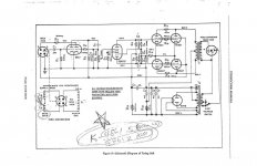
I don’t have a direct schematic link yet, which I’ll try to do this weekend, which seems preferable to sending people to a complete PDF manual elsewhere with a ‘see page 14’ instruction.
But this seems simple, so I’ll try describing. It’s the tuning unit of the Stroboconn, an AC source to drive the synchronous motor in the other chassis with the strobe dials.
Two push-pull pairs of 6V6GTA, B+ From 5U4GB (350 VDC) to CT of OPT thru a 100 ohm resistor (no UL taps).
One of the upper tubes and one of the lower tubes each have plate connected directly to ‘ends’ of OPT primary (325 VDC). Each parallel pair has a 47 ohm resistor between the plates (one is connected directly to the OPT, the other through the 47 ohm resistor).
The upper and lower pairs both have a 470 ohm resistor between their (control) grids. (One resistor per pair). Possibly a shared grid stopper. Two tubes have their grids capacitor coupled to the plates of a 6SN7GT phase splitter that each have 82k plate resistors fed from the 290 VDC (B+#2?, same source as 6V6 acreens).
All four 6V6GTA’s have screens connected together (290 VDC) to a common 4k dropping/decoupling resistor that goes to the 5U4GB (same 350 VDC the 100 ohm plate decoupling resistor is fed by).
All 4 cathodes are connected together and share a common cathode resistor of 125 ohms (unbypassed) to a common ground point. 19 VDC at cathodes per schematic.
The control grids have a little more complex compound connection I should leave for a schematic graphic. They are not symmetrical. The lower pair have a 150k grid leak resistor to ground, but the upper pair’s 150k grid resistor goes to a 10k resistor (160k to ground). The upper and lower tube that have no grid stopper before the coupling capacitor.
The 10k between ground and the 150k upper grid leak resistor goes to the ‘lower’ 6SN7GT phade splitter grid. Uh-oh, some kind of feedback?
There is no adjustment or measurement option to balance the cathode currents.
The questions (if this is a vivid and accurate enough description):
Do the 47 ohm ‘series’ resistors in one plate circuit ‘balance’ the current in each parallel pair like emitter resistors in parallel BJT’s? (I should use the analogy of separate cathode resistors, but something is holding me back).
Does anyone else think the grid stopper arrangement is marginal?
What I do know is that the signal level is uniform, other than aging, etc. in other words it’s set up and only adjusted perhaps in a calibration step.
I’ll figure out a way to link to a schematic image when I get home.
Thanks for reading, if not looking.
Tuning Unit amplifier
Stroboconn 6T5 Tuning Unit amplifier - Google Photos
Of course I am going to make some changes, but want to study/learn from the things I haven't seen before.
Stroboconn 6T5 Tuning Unit amplifier - Google Photos
Of course I am going to make some changes, but want to study/learn from the things I haven't seen before.
Last edited:
I’ll bet there is little interest in this, but you never know... maybe Enzo...
Characteristics of the L1/L2 tuning fork pickup & dual-drive-coil ***’y:
Schematic says L1 is approximately 215 ohms (DC). Mine is 277.6, and 101 mH at 60 Hz, 1 Vrms. Not defined, but I checked inductance as a shorted winding would likely result in leakage inductance order of magnitude measurement.
Dual L2 coil total resistance should be approx. 2 x 3400 ohms. Mine was between 6700 & 6800 ohms (DC). Inductance for the pair was 28.48 H at 60 Hz, 1 V rms. +100 cents on the fork dial would be Bb, 58.3 Hz. Couldn’t come up with 55 Hz for the fork at 0 cent mark...had to use 60. Just saw the pun...(Fork in A, man...3 octaves below A-440).
TBD what to do with the fork & transducer ***’y. Rubber shock mounts were pretty brittle.
Chassis is empty, ready to clean. Amp is out & inspectable...see if it matches schematic. I did note the 47, 470 and 125 ohm resistors of interest (to me) in prior rumination post...
Gotta check size of ClassicTone 40-41006 (I think that’s what I was looking at), but there is double the chassis space if I get the fork the fork outta there (pun #2).
...I’ll try describing. ...if this is a vivid and accurate enough description...
MUCH TL;DR.
Time it took to type that, you cudda put an image IN the forum posting so it would be handy even as external hosts go out of business.
The 10K.... how does the lower side of the driver get signal? This is a VERY common type of "phase splitter", you should know it.
"Grid stoppers" are for overdrive. This has an internal trimmer which is adjusted just to the edge of overload.
The 47 and 470 tube to tube... you think this is a low-frequency amplifier. But the tubes do not know that. They have gain to MHz. At those freqs the OT is a fat capacitor, every wire is an inductor, every electrode is a capacitance. A lot of little tuned circuits! When you strap two tubes together with non-zero length wires, and have the least capacitance each plate to other grid, you have a *push-pull* oscillator which may try to sing 13MHz. This will disturb the intended 55Hz signal several ways. But only if the tuned circuits are low-loss. Tossing a few Ohms in can damp the tendency to oscillate. In this build they are also jumpers, same cost as cutting and skinning a length of wire.
Tube idle current is moot: the amp only has to drive a motor. If it won't drive the motor, fix it. We are not looking for "sweet sound".
Attachments
- Status
- This old topic is closed. If you want to reopen this topic, contact a moderator using the "Report Post" button.
- Home
- Live Sound
- Instruments and Amps
- Stroboconn 6T tuner unit OPT?