") kkkkkkkkkkkkkkkkkkk
kkkkkkkkkkkkkkkkkkk^ hahah... true! pt-br is somewhat... ineffable
if i'd consider your friendly, humorous advice in portuguese regarding 'leaving the tHuBBiess (tubes) at peace' maybe my mind would go uneasy *laughs*
well, i'm back to this thread because i've studied and experimented further and learnt that the input resistor was too overkill for the modded circuit, so i've lowered it to about 1/10 of stock value
the results: less compression, hf attenuation, low mids thickened, less noise and squealing, more useable sweep in volume and gain potenetiometers... i'd say it was worth it!
a personal opinion: i've considered keeping this latest mod (input resistor) a secret for my own benefit, but its important to share it because i didnt achieve this great results by myself and its fair to contribute somehow...
i know theres people that doesnt want to learn, asking magical formulas taken by the hand, but the magic only happens if the person is not a lazy recipes copycat
even i get very stressed when my gear is on the workbench and gotta squeeze the brains out to make it work the way its needed, i dont like to work on this area, i only like to play guitar and nothing else!
but all techs and electronic masters have my deep respect, because its an art/science very hard and demanding... surely it's not for everyone;
maybe thats why i dont like to work on it and get stressed when i find aspects on my gear that doesn't fit my musical approach and need to be modded 'cause y'all know... affording new gear in Brasil is very expensive, quality wise!
i like to do easy things, that doesn't fail if i do it sloppy... its a necessary evil (if by any means my opinion mean anything)
anyway, thx u all, and... if something else changes on the circuitry, then i'll be back!
Last edited:
update:
-added local negative feedback loop on v1b;
-changed the dull/hf filter cap from 22n polyester to 28n pio;
-changed the pre tonestack / output cap from 47n brown chiclet pillow to 120n pio;
-added baxandall tone stack (ampeg specs) between the output cap and the output potentiometer;
-increased output potentiometer value from 100k to 250k;
i've done a considerable alteration in the pedal circuitry this week, but before upgrading the schematic attachment, i plan to make a major change that requires help from multiple minds:
since this pedal operates with 4 triodes/stages of gain in series and theres no need to have a fancy tube-clipper to mush out the tone, maybe its time to put two triodes in series, then parallel with another couple of triodes in series, properly biased;
the question is:
due to the nature of a tube, when pairing his own triodes, it behaves in such optimal way when associated in series or parallel?
----> the reason of this question is due to the fact that for me its the same effort if i series v1a + v1b, then parallel with v2a + v2b or series v1a + v2b, then parallel with v2a + v1b... or even parallel v1a with v1b to add in series with v2a in parallel with v2b
...
but the results of this possibilities require both theory and good experience, it could take much of my time to find it out alone, but it can benefit all of us if we cooperate
much thanks
since no one bothered to cooperate on the latest question...
...and i'm in a hurry to fix it to keep my carreer on the rails: rehearsing, jamming, songwriting...
...and the modded tube amps ended with a fantastic mojo that every time i engage the ht-dual of turbo rat into it, i feel like it is worth of playing the amps with no pedal...
..i've done some study and worked on this 'bottle rocket' pedal, since afaik it can be of worth if made the way i need it...
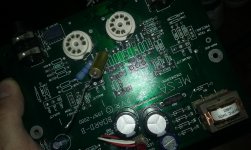
then i've realized this design unsuit my work, but i could salvage the chassis, socket, tubes, transformer, etc...
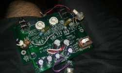
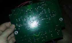
so, i've redesigned the pedal from scratch, using the board and some components, although most part of it i've ended pulling off;
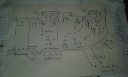
i'll describe the new circuit and even draw a quick scheme, but its easy to understand and i still need a little help to overcome some undesireable effects that i'll describe at the bottom of this post
since i've used the PCB, some jumpers here, some lifts there... some things might appear weird, such as v2 cathode resistor been not shared (v2b with 1k, v2a with two resistors in parallell... one 1.5k and another with 2.2k in the bypass cap slot)
the ampeg baxandall tone stack will be placed between v2 coupling cap and the volume pot, but i've decided not to bother with it for now and run tests if the pedal at least work;
then, i've put it to work... it works, the gain and volume pots work and respond well;
i've found issues on the test run:
1- when disengaged, the pedal change the tone, affecting wave smoothness, dynamics and note decay (this issue doesn't happen when the pedal is not fed by the power transformer plug)
2- on maximum settings, its draining in some radio station, but not much
3- note decay and smoothness seem artificial sounding, but the dynamics are very weirdly sensitive
on overall, i enjoy the overdrive its providing, from a boost to crunch and the maximum settings now are useful... a very enjoyable velcro fuzz, cuts well through the mix
i plan to use this pedal as guitar boost/drive/fuzz, but as well as a tube preamp for anything that requires the job done, by that i mean a clean preamp on lowest gain settings
for the radio interference, i kind of understand and have clues to overcome/filter it, but i have no idea on how to fix the bypass problem when the unit is disengaged and powered, same for the weird note decay and etc...
thanks for your time reading, please support me by pointing the design flaws and filters required
edit: the schematic drawing is the last image attached
...and i'm in a hurry to fix it to keep my carreer on the rails: rehearsing, jamming, songwriting...
...and the modded tube amps ended with a fantastic mojo that every time i engage the ht-dual of turbo rat into it, i feel like it is worth of playing the amps with no pedal...
..i've done some study and worked on this 'bottle rocket' pedal, since afaik it can be of worth if made the way i need it...
then i've realized this design unsuit my work, but i could salvage the chassis, socket, tubes, transformer, etc...
so, i've redesigned the pedal from scratch, using the board and some components, although most part of it i've ended pulling off;
i'll describe the new circuit and even draw a quick scheme, but its easy to understand and i still need a little help to overcome some undesireable effects that i'll describe at the bottom of this post
since i've used the PCB, some jumpers here, some lifts there... some things might appear weird, such as v2 cathode resistor been not shared (v2b with 1k, v2a with two resistors in parallell... one 1.5k and another with 2.2k in the bypass cap slot)
the ampeg baxandall tone stack will be placed between v2 coupling cap and the volume pot, but i've decided not to bother with it for now and run tests if the pedal at least work;
then, i've put it to work... it works, the gain and volume pots work and respond well;
i've found issues on the test run:
1- when disengaged, the pedal change the tone, affecting wave smoothness, dynamics and note decay (this issue doesn't happen when the pedal is not fed by the power transformer plug)
2- on maximum settings, its draining in some radio station, but not much
3- note decay and smoothness seem artificial sounding, but the dynamics are very weirdly sensitive
on overall, i enjoy the overdrive its providing, from a boost to crunch and the maximum settings now are useful... a very enjoyable velcro fuzz, cuts well through the mix
i plan to use this pedal as guitar boost/drive/fuzz, but as well as a tube preamp for anything that requires the job done, by that i mean a clean preamp on lowest gain settings
for the radio interference, i kind of understand and have clues to overcome/filter it, but i have no idea on how to fix the bypass problem when the unit is disengaged and powered, same for the weird note decay and etc...
thanks for your time reading, please support me by pointing the design flaws and filters required
edit: the schematic drawing is the last image attached
Attachments
Last edited:
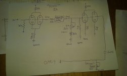
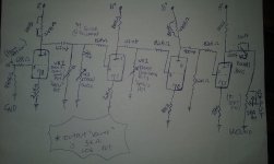
as attached below, the new schematic
good news! now the sound is approaching to a very desireable state
*new v1 plate resistor: 33k + 100k pot/variable resistor in series (gain pot... not a gain pot really)
*added baxandall tonestack between v1 and v2
*added v2 grid stopper
*new v2 plate resistor: 33k + 50k pot/variable resistor in series
the oversaturated with weird dynamics and synthetic note decay could be addressed to the former 100k plate resistor, seen as 200k equivalent by the parallel triodes, on lower Z plate resistor, the sound become more suited and i've found a mid term optimal biasing value
i realized the bypass is colouring the tone and theres pop-click when i engage/disengage the unit footswitch
the RF interference is gone btw
i'll consider tweaking with a low capacitance bypass on the cathode resistor, theres too much bass... since i want this pedal to be closest to a hifi preamp, i'll see what can be done to overcome the huge bass in the guitar overdrive without compromising the hifi possibilities
yet i expect advisal to make this pedal work properly quicker and leave the hell out of y'all at peace *laughs*
so in resume... big bass problem, switching/bypass problem
thx
signed
//punk
Attachments
Last edited:
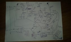
woah! i've discovered a great fuzz by mistake
trying to achieve a good hifi james preamp that lets me boost guitar signal aswell, i've discovered a fuzz in the style of 'sunface' / 'fuzzface' and 'fuzz 69'
check the schematic below and confirm by yourselves...
its got great dynamics and low noise, warm fuzz tones
woah! i've had to write down this recipe, but i will tweak this circuit a bit more, because i aint looking for this kind of effect anyway, besides its great sounding and doesn't have the cons of the germanium fuzzes (plus the passive baxandall eq)
this is my gift for you guys... hope ya'll like it
lots of mojo in it
Attachments
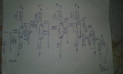
schematic below...
*very stable;
*lots of headroom, lots of gain;
*james tonestack, no muddy low frequencies below guitar range, no annoying high frequencies/feedback/squeal... only useable guitar frequencies, full of rich harmonics, sustain and dynamics;
*no radio interference (i live in a wooden challet, in the hills, close to alot of broadcasting stations);
well, i've had a nice break since i've decided to pull off the turbo rat's diodes and add some little extra capacitance between the compensating pins (tonal bliss, no more loss of dynamics, pure op amp clipping/mayhem)
then i've got the enough inspiration to finish this tube pedal (the blackstar ht-dual is hybrid, its pretty cool, but too perfect-ish)
its done, yay!
the popping switch noise was leaky PIO caps, i've realized they leak DC and are no good for me... i've pulled all pio caps out from my gear (guitar, amps)
this stuff really doesnt change the tone as some folks said, its true... its better to stick to stable components and be happy with reliable gear... i do have golden ears and this religion about some components are not a subject of discussion, since it doesnt benefit the performance of the equipment;
the best thing we can do is trust engineers that studied and experimented most, at first their claims might seem skeptic or 'tone lacking-wise' but i've wasted time arguing and experimented to find out this 0,000001% stuff doesnt change tone/timbre at all
a silent, stable device is the way to go
i hope this knowledge/ statement helps
thanks for the ones who helped
//end
Attachments
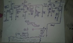
upgraded version
-better overall sound
-no hum
-now true bypass (use braided/ teflon insulated instrument cable)
-no rf interference
-no squealing on all settings
-plenty of gain for fuZz/dist settings
-plenty (loud!!!) of volume for boosting signal
-no tone sucking/loss when pedal is ON because of smart tonestack
great for both clean and dirty amps... no matter if tube or solid state based amplifier, when this pedal is on, there is bliss...
THE MOST IMPORTANT THING TO COMMENT ABOUT THIS UPGRADE: the pedal is better ONLY because of the bright orange led added, all the feel and vibe comes from this tubey orange glow...
Attachments
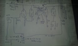
I didn't read through the whole thread, but did skim the original and compared to your latest schematic. It seems you've basically used this as a platform for your own thing. Pretty cool.
FWIW, the original is essentially a toned down Recto with a simplified / plate fed tone stack. There are simpler ways to achieve what you originally set out to do, but in the end sometimes tinkering is just too much fun.
Your LF/HF EQ placement is interesting (after stage 2), in that it controls more of the character of overdrive rather than acting as an overall tone control. I'm curious about the 100k load after the filters. Did you intend to load them down further?
Also, each stage has a 1M grid stopper. Was the OD too rough/bright? I'd imagine the response would be somewhat choked. But, guitar amp circuits rarely look right on paper.
Got any sound clips?
the pedal was cool as stock, but i needed less clipping, no mid scooping, increased dynamics, more note definition and louder output, so i've went all the way into what its the actual design
yes, the idea of this pedal is based in the od/ distortion controls: gain = ammount of signal to slam all stages, treble = ammount of treble distortion, etc...
most of what i've done was by experumenting, since i am not good in electronics
after this sunday gig i've realized it would be of an improvement if the bass cut gets relocated into the fx in, right in the 68k grid stopper before the signal reaching the first triode, because theres no other capacitor there to be seen in series with the bass cut, improving the control effectiveness and saving the earlier triodes from wasting power amplifying certain lowa
the treble cut will be relocated to the gain pot stage, so it will work exactly like a les paul 50's wiring volume + tone for guitars... i believe this approach will benefit from the co-op between both pots acting together as a grid leak with treble filtering;
the 100k grid leak with the filters was a bet to sweeten the signal and keep the tubes in a good operating point to decrease clipping and also to decrease the need for more attenuators/filters, mantaining the signal into less components, i had no clue if it would work in a good way
the 1m grid stoppers: a choice to mantain the headroom, clarity, noise stability and zero blocking distortion with no need for treble/rf/oscilation filters, i liked it mostly, but the increased resistance in series with the signal path gave a jet/high pressure/ jolty feel to the response... very 'shiny/sparkly/bright'
after moving the tonestack in the next upgrade, i plan to decrease the 1m grid stopper located in the sector where the 100k grid leak is placed, to see what happens... i think the stopper will be of 500k, if it works well, then i'll lower the 330k leak in the next stage into 100k and also halve the stopper from 1m to 500k
i think its gonna get better and wont be a waste of 4 triodes in series, even for a booster.
i have no audio samples, but i can record a video
you can also check our band demo songs to understand the kind of guitar tone/preferences that i'm into
so... now you understand that i dont understand much what i'm doing in theory, just been backed up by the experimentation with one or anotgher tip from the fellows of this forums, feel free to participate!
...i dont understand much what i'm doing in theory, just been backed up by the experimentation with one or anotgher tip from the fellows of this forums...
I was in the same boat, about a year ago. No formal education, I just jumped in and started modding my own amps, and eventually designed and built (and currently working on) my own amp from scratch. But I'm learning more and more each day, which is really the point.
Check out Uncle Doug on YouTube. He has some amazing videos on tube amp basics.
If I may give some suggestions, it would be to learn about attenuators, RC filters, capacitive reactance (which is directly related to filters) and input/output impedance of gain stages. Once you have a grasp on these concepts, it will make designing your own tube circuits much more predictable - and far less guess work/hoping for the best.
One tip I can give, is that putting the Bass EQ before the input stage will react with your guitar's output impedance (at the very least load down the guitar signal, attenuating it), and may not work as you expect. This is why you see passive eq's sandwiched between gain stages; to isolate the filter from outside influences. Simply moving the Bass to the first coupling circuit and leaving the treble at the second coupling stage (or vice versa) would be far more effective. But hey, maybe it'll work like a charm! Experimentation is a great teacher.
Good luck my dude.
Good luck my dude.
thanks
good to know this load down thingy about the caps
the rc filters and reactance such as the frequencies blocked by capacitance i've had to learn a bit
so, back to the bass cut closest to guitar pickups...
it might be good or not, if the attenuation doesnt inferfere in the feel and attenuate things that a grid stopper could do, then it might be positive because i'll balance the early basscut loaddown effect with smaller Z resistors for the grid stoppers
but honestly i think loading down the pickups might not result in a raw grip, of which is fundamental for what i like
your kind advices will be considered for sure and after the next upgrade i'll report what happened, but if you have a mobile PSU and a breadboard, you can also have this experience
PSU-wise... i am considering adding a choke to the power stage and lower some lytics, replacing them for film caps... i thought about putting an ez81 or so instead of diodes bridge, but tube rectification for a pedal might be too fancy for the benefits, even considering the fact that this pedal must be seen as a part of the single channel amplifier... the pedal's role is to be a perfect extension of the gain stages, not just a dirt/drive pedal to carry around, feed, stomp on and be glad for a mediocre clipping with a bit of sustain and noise added
*output / volume pot: 5k
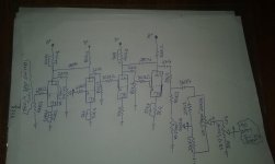
further upgrades
schematic added
conclusions on this run: compression can be considered a valid approach into taming 'loud level' foggy overdrive
high Z rp can lead to winter feelings due to the leaves falling from the tree in such kind of a rusty pattern, so clip the can into 'em!
maybe theres no need for a high Z grid stopper if the grid leak is also kept low
try it
Attachments
I suggest downloading Radiotron Designer's Handbook 4th edition. There's a ton of information in there, particularly Chapter 15 which deals with tone controls.
Your filters do things... but, no offense, are rather crude. The gist of it is, passive RC filters tend not to perform optimally as variable filters. In all honesty, for guitar amps the standard Fender TS is as good as anything ever designed. You can tack on a LPF (similar to your treble filter) for additional control.
Is there a reason that you're wiring your gain pot as a vari resistor as opposed to standard poteniometer? As you currently have it, the load presented to the preceding gain stages (dual ganged) isn't constant. Technically there's nothing wrong with that, and you're using a relatively large coupling cap so LF response isn't affected terribly. But, IME, the AC load does affect the tone (along with affecting gain) and having a constant load gives more predictable results.
The 5k output pot is extremely small load for the preceding stage - I suppose that's the reason for the large 0.22uF coupling cap. Again, not technically wrong (IOW, it'll work), but loading down a stage that heavily isn't optimal.
Respectfully, I really think you should study some schematics and figure out the basics of tube circuits. The Radiotron handbook has everything you'd need to know, but it's a tough read for a beginner. The original Mesa circuit of this pedal is actually based on a very successful circuit to begin with. Study that and figure out what makes it tick.
after all this experimentation doing weird things to the pedal, i've understood that its important to use cathode bypass caps and not to bother if its electrolytics or anything else
the downside of cathode degeneration is not worth the extra dynamics with clean headroom it has to offer
its important to experiment different plate values and hear what happens...
fwiw its nearly impossible to have both a hifi preamp and fuzz/drive on this circuit, so i've gave up the hifi thingy and approached into the guitar saturation for this pedal
the most conclusive finding so far is that when we plan to experiment 'wrong' design ideas, there can be results difficult to achieve by normal means
the pedal will reach its final version once i give up improving its flaws... i will need more time gigging with it to make up my mind if its good now...
Attachments
- Status
- This old topic is closed. If you want to reopen this topic, contact a moderator using the "Report Post" button.
- Home
- Live Sound
- Instruments and Amps
- Bottle Rocket tube pedal (made by Mesa/Boogie)