ok, now i'mma straighten up some misunderstanding...
the weird design on the previous circuit was due to a 3pdt switch problem... the only musician shop that sells 3pdt switches in my town had deceived me!
they pushed into me a cheap, worst quality chinese plastic 3pdt switch... one pin broke, it arced from inside... i had a lot of oscillation problems and tried to fix it with hardcore filtering and low Z grid leaks and 5k volume pot (the only thing that stopped the squealing)
after alot of research i realized it was a faulty 3pdt
the shop owner refused to aid me, he said his 3pdt was the hot stuff, there was no better switch than his blue crap, the fulltone bakelite 3pdt was LITERALLY the same as his product, i shouldnt bother with it, he also advised me to bulk purchase these switches from chinese site sich as aliexpress
then i searched @ fulltone website for some authorized dealers in my country and sucessfully ordered the real stuff: an original black 3pdt switch from fulltone, made of true stuff... no cheap plastics, sturdy bakelite!
it was day and night... then i've grounded the input on bypass and i could tweak the circuit into a better version
the funny thing is that i phoned the crappy shop owner to tell him i had bought a fulltone 3pdt and it was totally different and he was wrong into telling me that they were all the same etc... he didnt care *laughs*
well the schematic below will illustrate the current state of this pedal and honestly its running very well now...
again i thank all of u for help
and sorry for the bad design due to faulty 3pdt...
aww i had to spend $50 BRL for the bad quality 3pdt and another $125BRL for the fulltone...
at least im happy now and the pedal does what its supposed to
Attachments
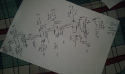
the previous design had too much gain, so aditional filtering with 'snubber capacitors' were added, but the problem root was the excessive gain...
i've put a 'big' cathode bypass cap on the first stage to deliver a full sound without suffering from cathode degeneration by feedback, so the following stages didnt need the cathode bypass cap, eliminating the need for filtering
after some tests, i've found out that the cathodes needed to be biased way softer with higher Z resistors, mellowing the signal and attenuating excessive gain;
so this is the current version and i've attached it to the schematics
sorry for posting and posting the updates, this time i've upgraded the pedal like 4-5 times before uploading a new version, but at least theres knowledge piled up for noobs to see what should not be done
at least theres visible and audible improvements
thx u all, hope it helps
Attachments
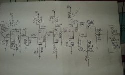
the attached schematic speaks for itself, very stable and even the clean tones out of it are great
reading my early posts/schematics kinda make me feel sorry for myself
but i wont delete the thread and repost the 'final' versions for the sake of knowledge and in respect to our forum fellows, i appreciate the kind advices and tips
try the pedal m8ys *lol*
*lol*
reading my early posts/schematics kinda make me feel sorry for myself
but i wont delete the thread and repost the 'final' versions for the sake of knowledge and in respect to our forum fellows, i appreciate the kind advices and tips
try the pedal m8ys
*lol*Attachments
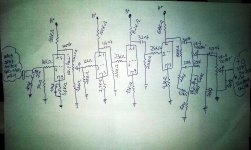
just to clear it up for dummies, since im sure the dear experienced fellows have got it easily:
INPUT SECTION:
*the 20/22nf cap from the sleeve/shielding input jack goes straight into the chassis
*the 183pf (sorry i only had handy 560pf caps so i've seried 3 of em, better write the exact stuff i've put into) from the hot input MUST be placed right with the 10k grid stopper, after the 3pdt or otherwise there will be tone sucking on the bypass;
****-----******~~~~~~~~
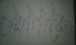
even sactisfied with the tone and the overall results, i've found an improvement in the output section and its my duty to report it:
*right after the treble pot, its wise to install a 33k resistor in series with the signal path, then the 560pf cap from hot to ground, followed by the 47nf capacitor, then the 100k output potentiometer with another 560pf capacitor from the wiper to the ground;
this will wield better electronic operation/performance
*to make things easier its just an added 33k resistor after treble pot*
awwwww thanks for 'lighting it up' <3
INPUT SECTION:
*the 20/22nf cap from the sleeve/shielding input jack goes straight into the chassis
*the 183pf (sorry i only had handy 560pf caps so i've seried 3 of em, better write the exact stuff i've put into) from the hot input MUST be placed right with the 10k grid stopper, after the 3pdt or otherwise there will be tone sucking on the bypass;
****-----******~~~~~~~~
even sactisfied with the tone and the overall results, i've found an improvement in the output section and its my duty to report it:
*right after the treble pot, its wise to install a 33k resistor in series with the signal path, then the 560pf cap from hot to ground, followed by the 47nf capacitor, then the 100k output potentiometer with another 560pf capacitor from the wiper to the ground;
this will wield better electronic operation/performance
*to make things easier its just an added 33k resistor after treble pot*
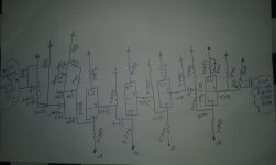
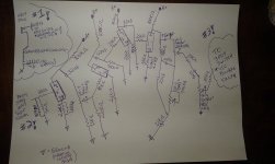
I turned Psicopanque's last image right side up, and turned the contrast up a little. It should be easier to study now.
Thanks, Psicopanque!
-Gnobuddy
awwwww thanks for 'lighting it up' <3
final version/period;
just to make it clear: i have environmental concerns, so the papers i use for drawing the sketches are reused in the back and after its full drawn, i reuse it as cover when i need to spraypaint things!
#2 sorry, really sorry for all the upgrades until reaching this ultimate level
#3 i couldnt get rid of the volume boost when raising bass and treble controls, but theres plenty of volume on tap for the output pot... and the tone & feel/playability are alright, so i gave up on trying to stabilize it since it works well
#4 thanks you all...
goodbye
//signed
Attachments
- Status
- This old topic is closed. If you want to reopen this topic, contact a moderator using the "Report Post" button.
- Home
- Live Sound
- Instruments and Amps
- Bottle Rocket tube pedal (made by Mesa/Boogie)