Hi there,
I've thought of making the Marshall Lead 100 Mosfet because of the opinions and reviews. They're so positive, and people say that it's probably one of the best solid state sounds, similar to tubes.
But I just want to build the power amp, because I'm going to use another preamp for it. I know that it's not gonna change the sound a lot, but I just wanna try that circuit.
Here are the schematics:

First of all, as I don't have much more experience in electronics (I've only built another 100 watt amp with 2SC5200), I don't know the resistor wattage, except for the 5watt (0.3ohm). I'm going to put them of 1/2 watt all of them. Is it a good idea?
I have the +49, gnd, -49 power source with a toroidal transformer and 2x4700 uF capacitors (63V), I think that's right.
Lastly, I don't know the function of the first two diodes (D1, D2). They are not necessary, aren't they? Just if the preamp is built, isn't it?
Do you think it is a good project idea?
Thank you so much for helping, JROW
The full schematics of the 3210 head.http://drtube.com/schematics/marshall/3210-iss7.gif
I've thought of making the Marshall Lead 100 Mosfet because of the opinions and reviews. They're so positive, and people say that it's probably one of the best solid state sounds, similar to tubes.
But I just want to build the power amp, because I'm going to use another preamp for it. I know that it's not gonna change the sound a lot, but I just wanna try that circuit.
Here are the schematics:
First of all, as I don't have much more experience in electronics (I've only built another 100 watt amp with 2SC5200), I don't know the resistor wattage, except for the 5watt (0.3ohm). I'm going to put them of 1/2 watt all of them. Is it a good idea?
I have the +49, gnd, -49 power source with a toroidal transformer and 2x4700 uF capacitors (63V), I think that's right.
Lastly, I don't know the function of the first two diodes (D1, D2). They are not necessary, aren't they? Just if the preamp is built, isn't it?
Do you think it is a good project idea?
Thank you so much for helping, JROW
The full schematics of the 3210 head.http://drtube.com/schematics/marshall/3210-iss7.gif
Last edited:
The Marshall power amp will certainly do its work when built properly, but I am not sure what should be so special about it? (Except that it uses long-obsolete MOSFETs?)
Apart from that, 1/2W resistors should do nicely.
The diodes at the input are for protection. You can leave them, but I would keep some form of voltage clamping, especially if you use a tube pre.
Apart from that, 1/2W resistors should do nicely.
The diodes at the input are for protection. You can leave them, but I would keep some form of voltage clamping, especially if you use a tube pre.
I owned that Marshall. The gain channel was useless but that has nothing to do with its power amp section. My understanding is that MOSFETs function in a manner that is somewhat similar to tubes is some respect. I've also read that this fact does not automatically mean they sound like tubes. I don't know if I ever cranked the clean channel nor if the output section was capable of overdriving or sounding like tubes.
This is just a power stage, nearly as simple as can be. Using MOSFETs rather made Marshall save a few components.
I remember trying one of the Mosfet series in a shop when they were available new, in the late 80s or so. Had only little playing experience then, but I did not like it, did not buy it - and did not regret it. They were meant as a cheap(er) alternative to the "real" JCM800 series amps.
To see them on ebay for over $400 is ridiculous IMHO.
Yes, there are two power MOSFETs in the amp. For Marshall this was reason enough to write it on the panel. I doubt they make much difference.
Marshall later chose a different approach with their Valvestate amps, as they were working with current feedback on the speaker then. Don't know if this made the difference, but I have better memories of the Valvestate amps than of the Mosfets.
Last edited:
The IRFP's definitely 'aint equivalent to the 2SK/2SJ devices. They are a different technology with totally different characteristics.
Lateral FET's are available from the likes of Profusion:
Lateral MOSFETs | Profusion
Lateral FET's are available from the likes of Profusion:
Lateral MOSFETs | Profusion
With caps of rather small value like here, there is no need to select voltage just as low as possible. They are neither big nor expensive, also not good quality ones.
Simply choose 63V, this should be safe for all electrolytics. For C42 I would take 160V or similar. C44 could have less, but why?
If you build it, maybe also consider adding an adjustable bias (by R54). For best safety, I would put in a trimmer first, measure its value after adjustment and replace it with a fixed resistor then.
Last edited:
And what about capacitors? Can someone tell me a program that calculates voltage by putting schematics?
Thank you.
You could simulate a circuit like this using something like LTSpice. Click my signature line to see how its done
")
Hi!!
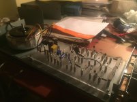
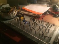
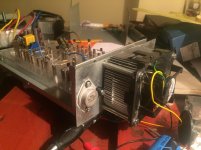
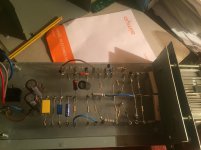
I've built the amp. This is how it looks like.
The photos are a bit old so they don't show the power transistors connected. Obviously they are now.
Okay, the amp works. It sounds pretty good and distortion, when the preamp volume is high, sounds incredible. Specially in low string riffs. It's... so natural.
But... volume is very low. I mean, to be a 100 watt amp, when volume is max, sounds like a 20-30 watt amp. In fact, I have a cheap 20 watt amp that sounds a little bit less in the same cabinet. And the fact is that the Mosfet amp sounds with a lot of distortion when volume is high. I don't want always that.
Also, when playing a big time, BUZ transistors don't get too hot. I think that's normal, or at least it was in the original 3210 head.
The amp doesn't make weird noises, and the sound is nice. But the volume... not for gigging.
So, as you told me, by R54 i could set bias. The fact is... I don't know how in this amp. In other threads they don't explain so well.
Please tell me the measurements I have to do in board and, if I put a trimmer in R54, I might start in 100ohm as in the original, and increase, or decrease, or what.
Thank you so much!!
(I used a 2x12 cab with 70watt celestion vintage v-type speakers, connected in 8 ohm config.)
Attachments
You set the bias by measuring the DC voltage across either of those 0.33 ohm resistors and using ohms law to derive a result.
The correct bias would be 0.1 amp for a single pair of lateral FET's but its not very critical. This means you should see 33mv (0.033 volt) across either of those resistors.
Some practical points...
1/ Ideally you should measure this with no speaker attached, however if the DC offset of the amp is very close to zero then having a speaker attached or not will not influence the result.
2/ The lower the value of R54 and the lower the current will be.
3/ I notice that the design does not have Zobel network on the speaker output which is normally required for total stability. Without using a scope to see what is happening its impossible to tell if there is a problem here or not but instability could appear as distortion.
4/ A single pair of FET's should be good for 70/80 wrms into 8 ohms. If it doesn't sound 'loud' before it all starts falling to pieces then I suspect something else is going on.
Please measure power output, ear reckoning of "loudness" isn´t very accurate.
1) confirm you have +/- 47V rails or are real close.
2) check that dummy load is actually 8 ohms
3) scope output to *see* clipping, which is more accurate than hearing it.
You will also see oscillation, unsymmetrical waveforms, gross crossove distortion, etc.
4) set a generator to 1 or 2V RMS or use some App to generate 440Hz or 1kHz, but Phone/Notebook/MP3 player headphone out usually supplies between 100mV to 200mV so you´ll need som kind of preamp.
5) put a 10k to 50k volume pot at the power amp input, set to 0.
Inject 1 to 2 V RS signal (check its value) to pot input, connect wiper to amp, start rising volume slowly while you check the scope screen.
6) once you start seeing clipping, back volume down a little so you barely reach it.
7) only now measure output V RMS and calculate power ... what do you get?
I´d expect at least 80/90 W RMS.
If you get 70W or even way less, say 10 to 30W, then there´s something WRONG which needs troubleshooting.
To begin with, rails will drop something, maybe down to 40V or so, that´s normal.
If they drop to, say, +/- 36/38V or less, your supply is quite inadequate for that amp.
But in any case, only testing and measuring will lead to an answer, just guessing is frustrating.
Well built, that power amp is good.
Which Mosfets did you use?
Where did you get them from?
The voltage in output is 0.1V. Is it normal, isn't it?
So I will measure what you tell me, Mooly, but it seems biasing won't change the loudness so drastically.
Thank you.
0.1 volts DC offset will be normal for that design (it is designed without attention to good DC balance) but having an offset like that means that you must measure the bias with no load attached. This is because the 0.1 volts will 'pull' or 'push' a DC current through the speaker, and that current will add or subtract from the small voltage across the 0.33 ohm resistor.
Biasing has zero effect on loudness.
- Status
- This old topic is closed. If you want to reopen this topic, contact a moderator using the "Report Post" button.
- Home
- Live Sound
- Instruments and Amps
- Building Marshall Lead 100 MOSFET