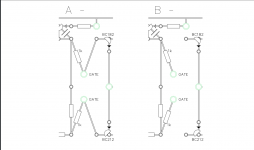
Which Mosfets did you use? Where did you get them from?
The FETs are a pair of BUZ900, BUZ905 from Farnell. In datasheet they put a power dissipation of 125watt instead of original sk134 and j49, which is 100watt channel dissipation.
Okay,
I've discovered a few things scoping the output of the amp.
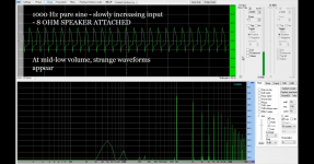
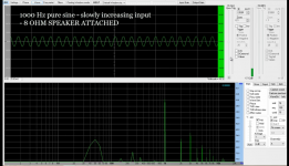
First of all, I was WRONG telling that the volume was low. The amp is able to sound strong, but the problem is that a distortion appears at a mid-low volume.
The distortion seems to be like a fuzz pedal. When the volume is low, the amp works without that distortion. It sounds completely clear, but quiet.
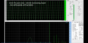
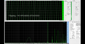
But scoping the output, I realised that the origin of distortion wasn't clipping: I injected 1 kHz increasing volume in a preamp, and these were the results.
View attachment input 1khz (convert-video-online.com) (1).mp4
As you can see, clipping is in a higher level than the distortion that makes the amp at a mid-low volume.
So, I measured the voltage in output, just before clipping in scope (no speaker attached). The AC voltage in output is 3.7 V. See what happens when I connect at this point the speaker. The distortion appears, and it sounds.
I tried it with a guitar too. When I'm playing softly, or at a low volume, it sounds clean. Even when I scoped the output without the speaker, the amp didn't seem to make the distortion that makes when I put a load to it.
View attachment ddd (convert-video-online.com) (1).mp4
And these were my attemps to solve the problem (surprise... no)
I put a TRIMMER in the R54 but I didn't change ANYTHING!!! I mean, the trigger was of 1kOhm, and in the schematic R54 was of 100Ohm. Okay, I set the trigger to 100 Ohm to go up or down... and when I put to 0 Ohm or to 1kOhm, the sine wave doesn't even react.
I put a gain pot (50k linear) in R61 (Originally 10k) but this reacted normally. As I increased gain, output was increased.
The problem is the distortion...Why?!!!
Hi voltwide,
This is how the rails looks like:
The amp switched on with -inf db signal: +47.9 V // -47.9 V
The amp switched on with low volume and no distortion: +47.7 V // -47.7 V
The amp switched on with maximum volume: +46.0 V // -45.8 V
I think this little drop is normal, isn't it?
This is how the rails looks like:
The amp switched on with -inf db signal: +47.9 V // -47.9 V
The amp switched on with low volume and no distortion: +47.7 V // -47.7 V
The amp switched on with maximum volume: +46.0 V // -45.8 V
I think this little drop is normal, isn't it?
I have seen two very obscure problems cause distortion like that.
1/ Having a ferrite cored inductive component in series with the load. This can be something as small as a ferrite bead slipped over one of the output leads somewhere. The material saturates and gives this weird distortion... more likely an issue at high frequencies though.
2/ Another inductive issue can be having a shared magnetic component (such as a dual wound ferrite core) in series with each rail. Mutual coupling between the supply currents again causes this odd effect.
Beyond that and its a case of scoping rails and seeing if anything is apparent. The volt drop is normal, however the rail should still remain clean though and with only a little ripple showing.
1st thing you say is impossible, I mean, there is no ferrite coil in series- parallel- or anything.
When I scoped output, and I refer to '8 ohm speakers connected', the load is 2x12" Celestion V-Type (16ohm) in parallel. It's not a problem of scoping, because distortion appears at same level (showed in screen), whether scoping is connected or not.
The only inductive problem that could be happening is that toroid transformer is inside of metal box. Idk if I should put it outside, but if I'm not wrong, toroid transformers make a very low noise...
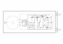
This is how the diagram looks like. Please take a look to discover any issue. Thanks!!

Last edited:
Just as an advance, too busy now to develop my answer: your amplifier is at present *heavily*current limited.
No problem in reaching rails and "voltage" clipping like any normal amplifier without load, but it can NOT drive an 8 ohm load.
Why?
Dunno yet, let me analyze the schematic (which I hope you posted earlier; if not, do now)
If I don´t remember wrong, that amp had transistor clamping current limiters (a.k.a. "short protection") ; if malfunctioning you will get that waveform.
But there are other possibilities too, so let me look at schematic first.
The waveform shows a square wave ... a *current* squarewave that is; the "weird shape" comes from driving an inductive load such as a speaker ... specially a guitar type one.
I mean remove them completely as a test and see if it 'fixes' your issue. The distortion may be the limiting cutting in to early. If that is the cause then you need to either run it without and accept the risk if the amp is abused, or redesign the limiter.
But first you need to prove that is or is not the cause.
But first you need to prove that is or is not the cause.
Tr10 and TR11 are current clamping/limiting transistors,for short circuit protection.
A damaged circuit might work too early, strongly limiting output current even when unneeded, so for testing purposes, let´s remove it .
Just remove diodes D10 and D11 , and retest amplifier.
A second possible problem is that you replaced source ballast resistors with wrong value ones, so recheck R67/R68.
Remember meters add own internal and wire resistance to displayed measurement so first short test leads , read display, and substract that value from what you measure across resistors.
Very poor precision, but if your end result is anything about 0.4 or 0.5 ohm, we can assume they are fine; if you measure 1 ohm or more they are not.
A third possible problem, after cheching and discarding 1 and 2 above, is that Mosfets are fake, because the ones you bought, if real, must work very well there.
4) just for kicks, measure DC resistance through the speaker cable, one end plugged in the cabinet, you measure at the free plug, to check what does the amplifier actually "see" ... we expect around 8 ohm there (again remember to substract meter parasitic resistance).
Do all tests and please post results, whatever you find.
I stumbled upon this thread with google because my love of the mosfet lead 100 is too strong! Great job so far. I have one which I love dearly but it picks up a lot of radio noise, so I'd love to learn from someone who knows the ins and outs of the amp to recreate one that's quieter and more reliable. Or at least the preamp if it can run off a DC supply as I'm a bit scared of working with AC power circuits and have a rack mosfet poweramp I can use it with. Did you recreate the whole preamp including the push/pull EQ knob?
I mean remove them completely as a test and see if it 'fixes' your issue. The distortion may be the limiting cutting in to early. If that is the cause then you need to either run it without and accept the risk if the amp is abused, or redesign the limiter.
But first you need to prove that is or is not the cause.
Okay, there are news.
Definitively that was a point. When removing the diodes, there was no current limiting, no distortion, and high volume. Now Im happy with loudness.
But I have a question.
1- I connected it in series with a bulb. Normally the bulb is off, but when I increase the volume and its high, the bulb (27W) starts emitting light like a vumeter.
I think I understand this, but please correct me. I think the dc supply is not enough, because at this volume, the rails are in +36V, -36V DC. But there is NO clipping still. So I think the 2 capacitors (2200uF) are not enough. BUT I dont know why - in the original amp these werw enough for the power amp. (?)(?)(?)
And another thing: shall I leave the circuit without the diodes? What will happen if there is a problem and there is short circuit in output?
- Status
- This old topic is closed. If you want to reopen this topic, contact a moderator using the "Report Post" button.
- Home
- Live Sound
- Instruments and Amps
- Building Marshall Lead 100 MOSFET
