Short version- am I an the right track/ any serious flaws?
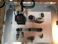
A few years ago I bought a Nutone intercom at a garage sale. Maybe $10. All I knew at the time was the 12ax7 was a good thing. Now I want to complete my vision. Most or the power supply is copied from the Nutone manual (took forever to find) The pre amp is basic fender.
I know i will have to play with bias and what not- any suggestions? (Other than build something else)
Attachments
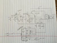
You are missing a grid to ground resistor on the power bottle, which will run-away and melt.
"Basic Fender preamp" is usually 100K plate resistors. Gibson and others swung to 470K. There is a difference in treble response. Either may be valid. Fender sold a few amps so I'd lean to his values. And you don't really need the small extra gain from high value plate loads.
You want a fuse on the wall-voltage side. 1A just so the line-cord can't start a big fire. You will of course also smoke-test with a Lamp Limiter, 100W Incandescent (or halogen) bulb.
Ground the Chassis!! 3-pin plug. Green to secure chassis bolt.
You are taking a lot of loss from 170V AC down to 120V DC. I checked your design; yes, at 50+mA the 6X4 will drop about that much. Ah, I see you stole the design; good policy.
You have an OT? If the NuTone sported that obscure 6CU5, that OT is sure to work, though maybe not with wall-breaking bass. (Probably break no walls with 2.3 Watts anyway.)
Last edited:
The 700r in the B+ filter *may* be excessive voltage drop. If that's how NuTone did it, fine. If you adopted it from another design, leave it, measure where the plate voltage comes to. The full 2.3 Watts of goodness needs near 120V. Of course you may be happy for less power if it plays well.
First- thank you!
Other first- grounding will be done, proper 3-wire and a fuse. I didn’t bother to draw it because it’s a ‘given’ but since I am a complete unknown and might be a lunatic you are wise to remind me.
100k fender plate resisters- I see that now. I took that value from the Nutone. I will start with Leo’s value.
I do have a Nutone OT- the original speaker is 3.2ohm- seems an odd value- I imagine a 4ohm will suffice.
And it is once again Nutones idea for the 700r in the B+, I will try to “breadboard” this before moving to a proper chassis
Thanks again, I know my blueprint is well beyond the the compression of the common man.
any suggestions? (Other than build something else)
No need to build something else......I made a few similar amps years ago but used 6AQ5 output tubes because I had lots of them, and they eat more B+ voltage. They worked well.
If the NuTone sported that obscure 6CU5, that OT is sure to work,
The 6CU5 is the 6.3 volt version of the common 50B5 which was replaced by the 50C5 to comply with the new UL spacing rules. Any OPT from an old radio will work fine. 2500 ohms was the most common flavor.
Nutones idea for the 700r in the B+, I will try to “breadboard” this
This was designed primarily for intelligible speech. Depending on what kind of music, and the playing style, you may want to experiment with the 700 ohm and 500 ohm resistors in the power supply. I'm sure that Nutone never dreamed that someone would plug a stomp pedal into this and set it on KILL!
If that's your style, lower the 700 ohm resistor a bunch. I tend toward zero. The plate voltage spec in these tubes was based on what you got from tube rectified wall outlet in the 1950's. The 6CU5 will eat 200 volts on its plate as long as you keep the screen voltage in the 110 to 120 volt range. This means adding some resistance to the 500 ohm resistor.
I think I used something around 2K ohms and no first resistor. My power transformers were liberated from some old RF signal generators and made about 250 volts of B+, and I used a 6AQ5.
The preamp is fed downstream of both resistors. The screen current stays in a relatively constant range, then shoots upward when the amp is driven to clipping. To maximize sag, sustain, and touch sensitivity you want the screen voltage and the preamp B+ to drop as you slam the amp into clipping. As the input signal dies out the screen current drops allowing the preamp B+ voltage to rise, increasing the total gain and helping that dying note to sustain longer.
Hence some experimenting with these two resistors will determine the amps "tone." The optimum values depend on your playing style, how hot your guitar's (or pedal) signal is, and the characteristics of the speaker. Most guitar speakers have a resonant peak somewhere in the guitar's frequency range. The impedance of the speaker hits 20 ohms or more at this frequency, so more plate voltage allows for more output around the peak. The impedance drops on either side of this frequency, causing more current to flow through the output tube, hence dropping the plate and screen voltage.
Also as stated put a 470K resistor from the 6CU5's grid to ground. The .02 cap across the OPT primary will kill treble, you may want to experiment with it's value or eliminate it. Fender and most others used 100K plate resistors on the 12AX7. These resistors affect the treble response, and the amps behavior when overdriven. They do not need to be the same value. Try anything from 47K to 220K or more. 100K works for amps with 200 volts or more of B+, but you might like something different.
The 43K? resistor on the grid of the first 12AX7 will also kill treble. It also helps stop interference from nearby AM radio sources. Anywhere from 1K to 68K is seen in guitar amps.
470K plates works OK for AM radio and intercoms, where you don't want much over 5KHz.
You might think the same would apply to e-guitar, where the high overtones are obnoxious and must be cut. But Fender's 100K passes out to 40KHz. There are two steep high-cuts in the system: the pickup top resonance and the speaker top cut-off. Apparently these are ample and maybe another low-pass in the amp is too much. I won't say this is Fender's biggest trick, but it may be a point. Also the 100K/1.5K values leave some gain and output behind but define a soft top-clip which may be musically pleasing.
3.2 is the DC resistance. 4 is the audio impedance around 400Hz. They are the same thing. W.E. tended to mark 4-8-16 being audio-heads. Cheap radio makers tended to use the number on their DC Ohm-meter, 3.2+/-.
You "never" see a 6.4 or 12.8 Ohm rating. If the speaker is in the same box, 3-4 Ohm is a part-penny cheaper (fewer turns of fatter wire). If the speaker is across the theater, 16 and 32 Ohm nominal audio impedance reduces loss in long lines. So there is a sharp division between box-radios(combos) and pro separates.
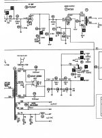
Here is the update ~ most of the change it should be included in this schematic.
The data sheet for the 6CU5 states that the maximum plate voltage is 135volts maximum screen voltage 117V seems it would be wise to stay within those parameters.
The 34k resistor on the first half of the 12AX7 is copied from the fender ‘champ’ and other fendor designs (the parallel 68 on input resistors.) I also added a 22K negative feedback, again from fender fame.
And I eliminated the “hum balance. I’m not sure what that was doing- I took it out.
The other question I have is for the 5000micromicrofarad (oops- no value labeled!but that’s what those are) capacitor‘s in the power supply by the 6X4- I don’t see those with other rectifying circuits. Anyone know about that?
Attachments
A couple of resistors for the heater supply tied to the power tube cathode? I am guessing the output transformer will be the weak link in the system. I doubt they put more transformer than was needed.
Not quite sure where these resisters you speak of reside? But the transformer actually powered several more tubes so I think it may be a strong link
")
.
And I eliminated the “hum balance. I’m not sure what that was doing- I took it out.
Do yourself a favor and leave it in. This keeps the filaments to a defined ground level, their windings should cancel hum pickup from the cathode then.
You have read it - it's only two resistors.
The other question I have is for the 5000micromicrofarad (oops- no value labeled!but that’s what those are) capacitor‘s in the power supply by the 6X4- I don’t see those with other rectifying circuits. Anyone know about that?
5000µµF
Long time I since I saw such a term. The engineers of that time obviously loved the power of ten. I wonder why they did not call it 5kpF These are suppressor caps, actually not uncommon in rectifier circuits. I think you can omit then. Stick to the heater balance resistors instead.
But the transformer actually powered several more tubes so I think it may be a strong link
Could it be you both are talking about different transformers?
Printer2 - I must apologize you clearly said “output transformer” and after further consideration I think I get the resisters comments
So this is what we learned so far... I can’t read, I am impulsive, and my lack of humility may result in a round of diy electro shock therapy. Perfect
you clearly said “output transformer” and after further consideration I think I get the resisters comments So this is what we learned so far... I can’t read, I am impulsive, and my lack of humility may result in a round of diy electro shock therapy. Perfect
...6CU5 states that the maximum plate voltage is 135volts maximum screen voltage 117V seems it would be wise to stay within those parameters. ...
Don't be chicken. 6CU5 is *probably* built on the 150V plate-stuff in the 25L6 tradition. Also 6CU5 is about the CHEAPEST tube you can blow-up; I found a price of $5 and I suspect if you hunt a while you can get a 10-pack for $25. It was made in small but not tiny quantity, and apparently didn't sell a lot on the re-tube market. (Who re-tubed their NuTone for better sound on the intercom?)
Also the 6Y6 and friends can work the same, with possible socket and bias changes. But that shoots the price way up: $7.
Yes, there's no rational point in hot-rodding a 1.3 Watt intercom to 1.5 Watts. Still won't fill the stadium; there's other amps for that. 1.3W may be "turn that down!!" in an apartment, and 1.5W won't be enough to drown-out the complaints. So I agree that staying inside Book Limits makes sense. It just isn't Rock'n'Roll.
no rational point in hot-rodding a 1.3 Watt intercom to 1.5 Watts.
No, the few extra milliwatts afforded by some extra B+ will not make much difference in loudness, but the extra voltage headroom to allow for some downstream sag to the preamp stages will change the entire character of the amp.
6CU5 is *probably* built on the 150V plate-stuff in the 25L6 tradition.
The 6CU5 IS a 6 volt 50B5. The first version of the little screamer I built for the HBAC amp challenge used a pair of 50B5's, a 12AV6 and a 12AU6 series wired operating from an isolation transformer. I experimented with B+ voltage from 120 volts to well over 200 volts to find the sound that I wanted. There were no issues operating 50B5's well over 200 volts.
Since the easiest and cheapest B+ voltage choices derived from rectified isolation transformer are 170 volts (full wave bridge) or 340 volts (voltage doubler), I needed to use one of those voltages to minimize cost. The 50B5's will actually live on 340 volts, but the idle current must be in the 10 mA range to avoid over dissipating the tubes, and that just didn't sound good (ugly crossover distortion). I later switched to 32ET5, 18FY6, and 18FW6 tubes because they draw less heater current and are on the dollar menu so the whole amp used $4 worth of tubes.
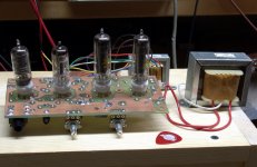
The schematic is here. This little amp can go from mild and clean to full metal racket just by rolling into the volume knob on the guitar. It is currently the only working guitar amp that I have, and sees use several times a week. It still has the original output tubes in it and the B+ is 170 volts. Screen grid and preamp voltage is about 125 volts until you hammer it hard and then It will drop below 100 volts.
Note....the 18FW6 is an 18 volt 6AU6 which is very similar to the old 6SJ7 pentode used in the Fender 5C1 Champ. The mosfet / pot on the plate allows for a variable plate load allowing the input stage gain to be adjustable from a little, to about 50 dB. The 18FY6 is half a 12AX7. The second mosfet is the phase inverter for true push pull operation. At the time of the original challenge the entire amp could be built for under $50 in parts.
Also 6CU5 is about the CHEAPEST tube you can blow-up; I found a price of $5
I can blow up cheaper tubes, but to get tubes for less than $1 you have to buy a bunch! The 6CU5 is on the dollar menu at ESRC. $10 minimum order though.
Summer Dollar Days - Vacuum Tube Sale - $1.00 Vacuum Tubes
the 6Y6 and friends can work the same
6Y6's are a bit rare and sometimes pricey. The 12L6 and family (6W6, 12L6, 25L6, 50L6, 12W6, 25W6, and 6GC5) all have the same guts and all but the 6GC5 are octal. The 6L6 and 35L6 are different tubes. The 6GC5 is a fat 9 pin miniature tube. Regardless of what the book says they will all work fine with 300 volts on the plate. I have cranked 40 watts out of a pair on 400 volts, but that IS pushing it a bit. As with some of the small tubes, the plate voltage can be bent a bit (OK a lot) but you MUST respect the screen grid ratings, or meltdown WILL occur.
Attachments
I am humbled by the Tubelab example- beautiful amps.
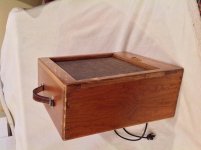
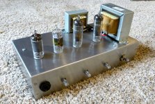
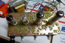
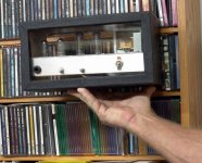
It looks pretty now, and I have found the Tolex covered box that it went in, but I haven't married the two yet.
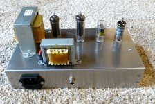
It started out as a piece of perf board with parts sky wired all over it and an entry in the Hundred Buck Amp Challenge. Picture #1.
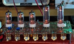
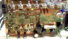
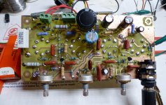
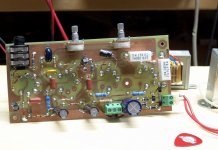
Then it lost a tube, but gained a real PC board and the Tolex covered box(which didn't fit exactly right). Picture #2 the board is sitting on the speaker cabinet I made for it (given away). Pic #3 shows the board, Pic #4 shows the amp in the box.
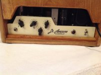
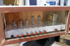
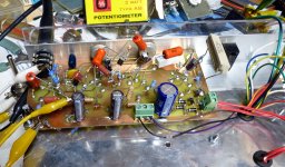
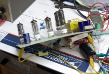
About this time, I lost my job of 41 years, and had to pack up all the stuff in the house I had been in for 37 years and move it 1200 miles on 3 weeks notice. That's when I gave away the speaker cabinet and a lot of other stuff. Three years and two moves later I find this little guy stuffed in a box. I fired it up and decided that i didn't like it, so I decided to make some improvements. I hacked up the original (called amp 1.3) to create amp 1.4 in true sky wired style. Picture 5 shows the original amp all tweaked into something that ROCKED!
OK, it worked......but wasn't going back into the box, so I made a new PC board. It was the ugliest home cooked board I had ever made. I almost trashed it on site, but fixed all the bad spots and testerd it anyway. Pics 6 and 7. I liked what I heard, so I ordered a little Hammond metal chassis from Mouser and stuffed it inside. That's what you saw in the previous posts, and that's why there are no pictures of the guts.....that PCB is ugly. I was going to make a new one, but it works, so.......that was over a year ago and it is currently my only working amp.
So back in the HBAC challenge, this little amp had a pair of bigger twin brothers.....One was a bad a$$, and the other, well don't make him angry.....because you won't like him when he's angry.....he gets really loud.
The twins have been found hiding in a box. Actually one of them lives in a box. The other one grew too tall to fit in the box (it runs EL34's and makes 40 watts). These will be investigated further in the coming months. I might even finish the box if I like the amp. It's been several years since I heard it but it was my favorite of the three.
Attachments
-
 Amp2.X_front_x.jpg675.4 KB · Views: 39
 -
 NoGlow_A.jpg273.8 KB · Views: 38
 -
 UnderTheDeck_A.jpg242.1 KB · Views: 30
 -
 NewBoardTop_x.jpg886.2 KB · Views: 23
 -
 NewBoardBottom_x.jpg802.4 KB · Views: 37
 -
 It Rocks_x.jpg838.2 KB · Views: 40
 -
 AlmostDone_A.jpg251.8 KB · Views: 41
 -
 Bottom_A.jpg205.1 KB · Views: 92
 -
 Testing_A.jpg206.6 KB · Views: 93
 -
 Amp1_0_A.jpg101 KB · Views: 103
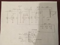
Here is a screen shot of the nutone schematic- it lies by the way. There is only one 6.3 volt secondary.
Question- the wiper on “r30” - the 250ohm humbalance- not grounded? I thought it would act as a “virtual center tap” - or is the connection to pin 1 on the 6cu5 having the same function, going to ground through the 220r?
Question- the wiper on “r30” - the 250ohm humbalance- not grounded? I thought it would act as a “virtual center tap” - or is the connection to pin 1 on the 6cu5 having the same function, going to ground through the 220r?
Attachments
- Status
- This old topic is closed. If you want to reopen this topic, contact a moderator using the "Report Post" button.
- Home
- Live Sound
- Instruments and Amps
- Petite boutique HELP