You have my sympathy!I'm so frustrated right now.
When I first got into electronics, this type of frustration was a frequent companion with every new project. I was a kid at the time, with no diagnostic tools at all, so it was hard to dig myself out of the holes I got into due to my novice skills.
One of the things that can happen is that each attempt at a repair creates a new fault (or faults). This happened to me a lot at first, mostly because of my poor soldering technique as a novice.
Anyway, my first suggestion is to take a nice long break. Do whatever relaxes you and makes you happy - take a long hot shower, play with the dog / cat / kid, go for a walk, enjoy that piece of chocolate that's been sitting in the pantry, whatever.
")
When you're refreshed and no longer frustrated, and ready to re-visit your amp, make a plan as to how you're going to approach the fault-finding.
I understand that you don't yet have a 'scope. That leaves you a little bit blind, but there are still at least two different fault-finding options, both involving tracing the progress of an audio signal through the chain (as you have already started to do).
Firstly, you need some sort of source of a steady audio signal. Playing your guitar as a test signal doesn't work well, because a guitar is large, cumbersome, and occupies at least one of your hands. So use your resources here. Ideally you would have an audio signal generator or function generator. If not, you can solder together a couple of transistors, resistors, and caps to make an astable multivibrator (Google if you don't know how). As a last resort, do you have an old MP3 player or phone you could play audio files through?
(Please don't use your shiny new $$$ iphone or Android phone, there is a possibility of frying it, and that will not make you happy!)
With the signal generator ready to go, first unplug the speaker from the amp, and connect the signal directly to the speaker. Do you hear a faint sound? Good, the speaker is working. No sound? You have either a dead speaker, or bad wiring to the speaker. Find and fix the problem.
Now plug the speaker back into your guitar amp, and power it up. Using extreme caution to avoid electrocuting yourself, apply your test audio signal through a small capacitor (say 0.01 uF / 500V rated) to the control grid of either output tube. You should hear a much louder tone from the speaker.
It works? Okay, try the other output tube (assuming push-pull). If applying the test audio signal to either output tube's control grid produces audio from the speaker, your output stage is working.
If not, break it down. Did one tube work? Then focus on the other one. Make DC voltage measurements. Power down, discharge filter caps, make resistance measurements. Inspect and measure continuity through solder joints. If you are methodical and test every single point where the circuit might have failed, you will find your problem, and be able to fix it.
Okay, let's say you have achieved success, and now you know the output stage of your amp, including OT and speakers, is working.
So you move your signal source back one stage, to the control grid of your phase inverter (if cathodyne), or to both control grids of the phase inverter (if a long-tailed pair). Best to disconnect any global negative feedback while doing this - it can confuse the issue a lot. As before, fault find if necessary, one step at a time, until you are 100% sure your phase inverter is working.
By now the method should be clear - you start at the speaker, and work back, one amplification stage at a time, until the signal disappears. When it does, you find and fix the fault (it will be in the stage you are currently testing), then resume the process.
At some point, you will find yourself applying a signal to the input guitar jack, and hearing a loud sound through your speaker. Now your amp is working.
There is an alternate approach to signal-tracing, which is closer to what you did: apply a small test audio signal to the control grid of the input stage, then use a small value cap (say 0.010 uF 500V) to pick off the audio at each successive stage of the amp, and run that audio into a small, low-power test amplifier so you can hear it.
The disadvantage of this method is that you need both a source of audio signal, and the little amp that you use to detect if the signal is present at each stage.
-Gnobuddy
At least you can rule out some faults by simply taking DC mesurements on the tubes. This will give you a hint whether you have trouble with a tube, its connections or supply.
A decent used scope won't cost you an arm and a leg either. I personally would even prefer some old-style analog CRT model for this work. They are bulky, but I definitely prefer the response of a CRT trace over a LCD screen. Plus a - for me analog - function generator to make it complete.
A decent used scope won't cost you an arm and a leg either. I personally would even prefer some old-style analog CRT model for this work. They are bulky, but I definitely prefer the response of a CRT trace over a LCD screen. Plus a - for me analog - function generator to make it complete.
I personally would even prefer some old-style analog CRT model for this work. They are bulky, but I definitely prefer the response of a CRT trace over a LCD screen.
+1 At almost* any price point a used, good analog CRT will be better value for money. Bulkier, hotter, less automated but better at seeing what's going on. And tougher & maintainable.
The new "stop here" point is about $500US where you can get into HP/Aglient/Keysight "InfiniiVision" product (used and the bottom end of new). These have "persistence" done in hardware (ASIC) rather than software so you've a much better chance of catching "the glitch".
Plus the automation and integration now available on modern digital gear...
The amp in question started its life as a bit of a project one of my buds made up for me; it was an Epiphone Valve special that he gutted (aside from the power and output trannies) and built a brand new all tube amp circuit inside.
Take a look at this thread on sewatt.com for how to mod the Valve Special successfully, www. sewatt.com/node/11921 It may be some help. You will have to login to acceds the thread.
Last edited:
I have some updates:
So I made an audio injector probe and started poking around in the circuit; and there is life! A lot of it actually... most of the circuit path will allow signal to pass... all except for the pin 1 and pin 6 of both the 1st 12ax7 of the marshall channel, and the only 12ax7 in the clean channel. V2a+b all function as they should; putting the audio into the grids or plates yields pretty load audio so amplification IS occuring.
But my main issue here is what the hell is going on with pin 1 and 6 on the 12ax7 stages? SHouldn't injecting audio push signal through the tube for amplification? I've tried different tubes in these spots too but to no avail; it isn't being fixed by that. I even bridged the gain pot on the marshall channel just to see if signal will flow past it and be amplified; but all that I get is very miniscule audio if you inject audio before the 470k resistor paralleled with the small cap, and miniscule audio if you inject it after words. Injecteding audio into pin 7 yields loud output of the music being played. The pins of the socket all have continuity, so what gives? What could be causing this??
I'm so confused, hahah
On a further note, it turns out if you play the guitar very loud, quiet output can barely be heard from the speaker.
Excellent, you are now on your way to fixing the problem. All that's left is to be 100% systematic about your fault-finding process.So I made an audio injector probe and started poking around in the circuit
Okay, this opens up specific possibilities. Perhaps you have mis-wired all your 12AX7s. Some possibilities:...all except for the pin 1 and pin 6 of both the 1st 12ax7 of the marshall channel, and the only 12ax7 in the clean channel.
1) Is the oddball centre-tapped heater wired properly? You have to parallel the two parts of it to run it off a 6.3V heater voltage (4 & 5 shorted, 6.3 V AC between pin 9 and the shorted combination pin 4&5).
Once you are sure the heater is wired properly and getting hot as it should, do the following DC voltage measurements on V1:
2) What are the DC voltages on pins 1, 2, 3, and the B+ end of the 100k anode resistor connected to pin 1?
3) What are the DC voltages on pins 6,7,8, and the B+ end of the 100k resistor connected to pin 6
There are a lot of ways to get it wrong, and only one way to get it correct (and working)! That 12AX7 might not work for a number of reasons. For example, you may have got the pin connections wrong, mis-wired the heaters, maybe there is a cold solder joint so no B+ on the anode resistors, et cetera, et cetera.But my main issue here is what the hell is going on with pin 1 and 6 on the 12ax7 stages?
Do the faultfinding steps I outlined above, keep thinking through every step, you will find the problem. The DC voltage checks I recommended will either point you straight at the problem, or narrow down the search so you can do your next diagnostic test.
With fault-finding a system like this, you just have to be 100% logical and test every possibility, until you find and fix every problem (worst case, there may be multiple problems).
And this is telling you it's not the tube, it's the circuitry around it. Most likely something is wired up wrong. Again, do the diagnostic tests I listed in this post...that's the way to find out what's wrong!I've tried different tubes in these spots too but to no avail; it isn't being fixed by that.
In my experience, getting miniscule amounts of signal usually tells you nothing. A high-gain, high impedance circuit like a guitar amp will respond to all sorts of tiny unwanted signals, in all sorts of ways that nobody anticipates, and that doesn't help you narrow down the source of the much bigger problem you are looking for.all that I get is very miniscule audio if you inject audio before the 470k resistor...
Most likely a miswired socket, or bad solder joints. But guessing is rarely helpful when troubleshooting - so (if you ever watched anything Star Trek related) be as Vulcan as you can be, set aside your emotions for now, be calm, methodical, systematic, do all the diagnostic tests I just listed in this post.What could be causing this??
You will get it working if you are methodical and systematic, and when you do, that's the time to become human again, and enjoy the surge of satisfaction and happiness that comes with success!
-Gnobuddy
V1 pins
1:229v
2. .3mw
3. 1.956v
4. 4.16v ac (6.8ac between 4 + 9) 20.1v dc... seems a little high yet tubes are dim
5. Bridged with 4
6. 261v
7. .5mvish
8. 4.4v
V2.
1. 304v
2. 262v
3. 263v
4+5+9 all the same
6. 200v
7. 1.2mv
8. 1.537v
V3 (seperate channel)
1. 135.5v
2. .8mv
3. .333v
6. 175.6v
7. 135.4
B+4 304v
B+3 308v
B+2 342v
B+1 355v
6v6 pins
1. .1mv
3. 333v
4. 353v
5. .2mv
6. .1mv
Output transformer
357v primary common
333v 5k primary
To further complicate things, just for ***** and giggles I threw in some of those JET CITY solid state tube replacement things (Retrovalves) and I get strong signal that passes through the amp; however it does not sound like the amp used to (ie. no distorted tone) and its very anemic. Not only that but at certain settings, there is a rather loud oscillated tone. For example, if the gain is up and treble is down all the way, it'll oscillate. If gain is down and treble is up, it'll make weird noises and such.
The amp still sounds 'passable' if you use the retrotube in v1 and a real tube in v2, however, if you use a real tube in v1 and a retrotube in v2, its VERY quiet/no output again, which is the same effect that occurs when two normal tubes are put in the amp.
It almost seems like something in stage 1 is choking the signal; but I have no idea what would cause that. I've run my probe through everything, and like I said in my previous post, the problem is isolated on pins 2 and 7 it appears as no signal can really choke through, yet when applying signal to pin 1 you get little output, or pin 6 you get STRONG output. None of that makes any sense....
I see no blown fuses, nor bad diodes (although I honestly wouldn't know how to check if a diode is good or not). I refluxed every solder joint and swapped around some bad wire. All resistors read true to their values, and none of the caps appear open.
Also the pre-amp tubes glow very dim; before this whole fiasco occurred, they glowed rather brightly when the amp was used.
What I don't understand here is that this amp was working fine; it was working VERY GOOD before I tried to put the new classictone output tranny in, and then all of a sudden everything stopped working and replacing the tranny with the original one made no difference!
I'm honestly stuck; I can't find a single problem in this circuit that seems obviously fixable and I have no clue what putting a new OT in could have done to give me these current issues.
Is it possible the PT is shorting out and causing not enough current to be delivered to the tubes, and thats why the solid state retrovalves will work??
I'm lost, lol
Is there a schematic somewhere?
Just had a look at the thread but I think I missed it..
What about pin #8?
#1 an #6 are not connected, therefore useless.
Screen voltage (4) is too high.
What tube is V3?
Just had a look at the thread but I think I missed it..
Something could be wrong here...are you sure pin numbers are counted correctly?6v6 pins
1. .1mv
3. 333v
4. 353v
5. .2mv
6. .1mv
What about pin #8?
#1 an #6 are not connected, therefore useless.
Screen voltage (4) is too high.
What tube is V3?
Last edited:
v3 is a 12ax7. It has its own separate path to the power amplifier so is pretty much an 'amp-within-an-amp' so to speak.
Number 8 I believed was around 21v? I can't remember and I'm not sure why I didn't write that one down, lol.
Even if the power amp is not exactly biased correctly/set up correctly, it still works and outputs a signal so I'm pretty sure that it's not the main problem that this stupid project is giving me, hahah.
I can't find any physical faults in v1 though and its driving me mad.
I just ordered some of the cheaper resistors and caps and will probably just replace everything in that part of the circuit just so I can be 110% sure it isn't some weird thing going on... may replace the tube socket too...
its 5:22am here and I'm still up just trying to research what could be going on with this amp, and I have work at 10am
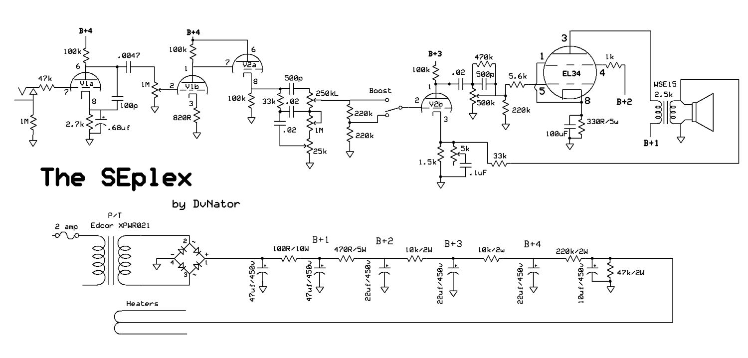
Here is the schematic.
Only problem is I have a different power amp and power supply layout since it was a friend of mine who initially built the amp. I just tweaked the preamp section (well, rebuilt the whole pre-amp section) to match what's going on in this schematic. And it sounded great for a few weeks!!! It just stopped working after I spent 3 gosh dang days building a cabinet for the amp and installing my new, not cheap output transformer which somehow broke the perfectly functioning amp. ughhhhh
Number 8 I believed was around 21v? I can't remember and I'm not sure why I didn't write that one down, lol.
Even if the power amp is not exactly biased correctly/set up correctly, it still works and outputs a signal so I'm pretty sure that it's not the main problem that this stupid project is giving me, hahah.
I can't find any physical faults in v1 though and its driving me mad.
I just ordered some of the cheaper resistors and caps and will probably just replace everything in that part of the circuit just so I can be 110% sure it isn't some weird thing going on... may replace the tube socket too...
its 5:22am here and I'm still up just trying to research what could be going on with this amp, and I have work at 10am
Here is the schematic.
Only problem is I have a different power amp and power supply layout since it was a friend of mine who initially built the amp. I just tweaked the preamp section (well, rebuilt the whole pre-amp section) to match what's going on in this schematic. And it sounded great for a few weeks!!! It just stopped working after I spent 3 gosh dang days building a cabinet for the amp and installing my new, not cheap output transformer which somehow broke the perfectly functioning amp. ughhhhh
21V on the 6V6's cathode is ok.
I think the screen voltage may be too high given the current plate voltage, but you are right, this is not the real problem. Save this for later.
But here is something else:
This may be the point where you lose the signal. Is this a 12AX7?
4,4V on pin 8 is not ok. Wizh this voltage the triode will be blocked. How is pin 8 connected? Is this exactly like in the schematic, where the 2k7 resistor is? Check the value and connection of the corresponding cathode resistor. If they are ok try to remove the 100p capacitor for testing, it could be leaky.
Ok, sorry for the confusion with the schematic. I thought you would refer to a different one.
I think the screen voltage may be too high given the current plate voltage, but you are right, this is not the real problem. Save this for later.
But here is something else:
V1 pins
1:229v
2. .3mw
3. 1.956v
4. 4.16v ac (6.8ac between 4 + 9) 20.1v dc... seems a little high yet tubes are dim
5. Bridged with 4
6. 261v
7. .5mvish
8. 4.4v
This may be the point where you lose the signal. Is this a 12AX7?
4,4V on pin 8 is not ok. Wizh this voltage the triode will be blocked. How is pin 8 connected? Is this exactly like in the schematic, where the 2k7 resistor is? Check the value and connection of the corresponding cathode resistor. If they are ok try to remove the 100p capacitor for testing, it could be leaky.
Ok, sorry for the confusion with the schematic. I thought you would refer to a different one.
Last edited:
Something is wrong with the wiring around pin 8. The voltage there is too high. Check solder joints at both ends of the 2.7k cathode resistor, also check if it is really 2.7k (maybe it's the wrong value, for example, 27k instead of 2.7k ?)V1 pins
1:229v
2. .3mw
3. 1.956v
4. 4.16v ac (6.8ac between 4 + 9) 20.1v dc... seems a little high yet tubes are dim
5. Bridged with 4
6. 261v
7. .5mvish
8. 4.4v
-Gnobuddy
Jarrod, you are perfectly right, making random changes like that really does further complicate things, and makes it much harder to find out what is actually wrong.To further complicate things, just for ***** and giggles I threw in some of those JET CITY solid state tube replacement things (Retrovalves) and I get strong signal that passes through the amp;
I do understand that you are frustrated and impatient, and that is why you are making random changes. But please remember that this is not a good way to diagnose a fault. You have to make a systematic diagnosis, as I have been trying to say for several posts now.
Right now, we know something is wrong with the wiring from V1 pin 8 to ground. That is the place to focus your efforts, until that particular problem is found and fixed. (There may be others too.) One step at a time, fixing each problem you find as you go. If you do this, you WILL eventually have a working amp.
If, on the other hand, you keep making random changes, you will continue to muddy the waters, and maybe create more faults as you go. This is a guaranteed route to lots of frustration and delay.
The Retrovalves swap only tells you that Retrovalves will work (badly) even if there is a mistake in the wiring between pin 8 and ground, while an actual valve (12AX7?) will not work with the same mistake. This bit of information, unfortunately, is useless in terms of actually fixing the problem you're trying to solve.
At bottom, these valve circuits are very simple. Get the heater to the right temperature, make sure the right DC voltages are on grid, cathode and anode, apply the right AC signal to the grid, and it WILL work. Ergo, if it's not working, one or more of those (few) conditions is not being met. All you have to do is methodically track down and eliminate the fault(s).
-Gnobuddy
Sorry, I missed your post earlier. And yes, I agree with you!Great minds think alike.
-Gnobuddy
V1 pins
4. 4.16v ac (6.8ac between 4 + 9) 20.1v dc... seems a little high yet tubes are dim
The DC voltage here has nothing to do with the actual heater supply. The whole heater potential is deliberately elevated above GND by the last two resistors in the supply chain.
This is done because the cathode voltage of the cathode follower V2a is quite high and might do damage to the fragile heater-cathode insulation inside the tube. To lower the voltage difference between cathode and heater, the DC potential of the latter is made higher. The heater sill runs at 6.3V, but this voltage "floats" 20V above GND in your case.
But....
20V seem fairly low. Given your B4 voltage and the values of the elevation resistors I would expect rather 50 than 20 volts.
Your amp does not really use the same pins as the schematics, does it?V2.
1. 304v
2. 262v
3. 263v
I suppose these pins are actually what the schematics read as 6, 7, 8, right?
And the 4.4 voltage was measured on the 820 resistor of V1b, not on the 2k7?
This would explain why the voltage on your pin 3 of V2 (which I suppose to be pin 8 of V2a in the schematic) is also way too high. At this point you have 240 Volts of between the cathode and the heater. This may even damage the tube.
So, take a close look at the V1 7 pin 8 where you got these 4.4V. Eliminiating the problem is most likely to fix the problem on V2a too.
edit:
HA...! Is it possible that by mistake the 820 Ohm resistor is 8k2 in your amp??? This would about match the readings.
Also check the value of the 100k plate resistor.
Last edited:
- Status
- This old topic is closed. If you want to reopen this topic, contact a moderator using the "Report Post" button.
- Home
- Live Sound
- Instruments and Amps
- SEplex style build questions (fizz, fuzz, fart?)