Hey guys, I'm pretty new around here! I actually joined up here because I was having trouble with this DIY amp of mine and was having a couple of odd issues with it.
The amp in question started its life as a bit of a project one of my buds made up for me; it was an Epiphone Valve special that he gutted (aside from the power and output trannies) and built a brand new all tube amp circuit inside. It was great for cleans, but not much else honestly. It also used 3 12ax7s, 12 utilized for one clean channel, and 1 for a different, separate clean channel.
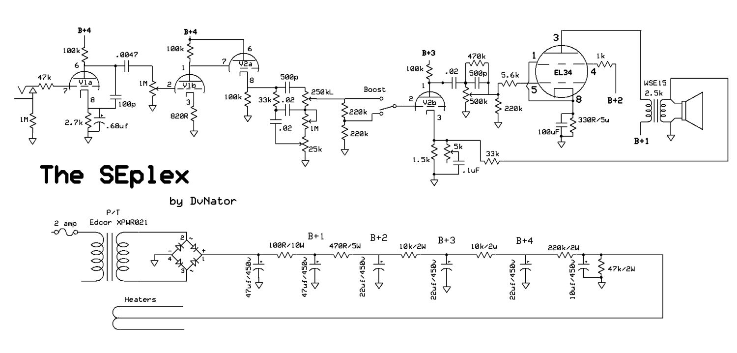
I have since modified the 2 12ax7 clean channel to the topology that the SEplex has, and although it sounds pretty great, there is some odd sort of fuzzy/hissy/farty quality to the distorted tones. Clean and crunch sound very good, but the overdriven tone sounds like it has some sort of 'swirl' to the sound, and its more harsh on the lower strings.
At full gain, chords seem to 'compress' in volume. I've upped some of the grid stopping resistors in the preamp, and the grid stopper for the el84 already seems very high (100k resistor in series with a 2k resistor?? Not sure if that is a mistake or not but there DEFIANTLY is no lack of high end in this amp) so I'm not certain its lack of blocking resistance. Also, all coupling caps are .02, just like in the SEplex so I'm not certain its that either.
Could it be that the output transformer just can't handle the amp as it is? It doesn't seem to be dependent on volume; just the pre-gain.
Thanks for any help you can provide me with!
ON A SIDE NOTE:
If I wanted to say, convert the power section to a dual el34 design (I have a 100w PP power tranny and output tranny hanging around from a busted amp), would I have to make huge changes to the power supply as is, or should that be able to remain unchanged? I'm not very well educated with power amps and how transformers, both output and power are rated and utilized. I do have a relative understand on pre-amp circuitry however and realize I'd likely have to convert the clean channel 12ax7 into a phase inverter if I made this push pull; but that's not such a big deal to me.
Thanks!
-Jarrod
The amp in question started its life as a bit of a project one of my buds made up for me; it was an Epiphone Valve special that he gutted (aside from the power and output trannies) and built a brand new all tube amp circuit inside. It was great for cleans, but not much else honestly. It also used 3 12ax7s, 12 utilized for one clean channel, and 1 for a different, separate clean channel.
I have since modified the 2 12ax7 clean channel to the topology that the SEplex has, and although it sounds pretty great, there is some odd sort of fuzzy/hissy/farty quality to the distorted tones. Clean and crunch sound very good, but the overdriven tone sounds like it has some sort of 'swirl' to the sound, and its more harsh on the lower strings.
At full gain, chords seem to 'compress' in volume. I've upped some of the grid stopping resistors in the preamp, and the grid stopper for the el84 already seems very high (100k resistor in series with a 2k resistor?? Not sure if that is a mistake or not but there DEFIANTLY is no lack of high end in this amp) so I'm not certain its lack of blocking resistance. Also, all coupling caps are .02, just like in the SEplex so I'm not certain its that either.
Could it be that the output transformer just can't handle the amp as it is? It doesn't seem to be dependent on volume; just the pre-gain.
Thanks for any help you can provide me with!
ON A SIDE NOTE:
If I wanted to say, convert the power section to a dual el34 design (I have a 100w PP power tranny and output tranny hanging around from a busted amp), would I have to make huge changes to the power supply as is, or should that be able to remain unchanged? I'm not very well educated with power amps and how transformers, both output and power are rated and utilized. I do have a relative understand on pre-amp circuitry however and realize I'd likely have to convert the clean channel 12ax7 into a phase inverter if I made this push pull; but that's not such a big deal to me.
Thanks!
-Jarrod
...If I wanted to say, convert the power section to a dual el34 design (I have a 100w PP power tranny and output tranny hanging around from a busted amp), would I have to make huge changes to the power supply....
I have a 9HP lawn tractor. Can I put a 300 horsepower Mustang engine in it?
Actually, the guy up the street "did". There is a lawn-tractor race club around here. Gol-danged V-8 on top of the teeny front tires. But LOTS of mods to the driveline. And I suspect he can't really get all 250HP through the small rear tires to the ground; it may be more smoke and noise than actual GO.
No, the original power is basically all you will get until you replace Major Parts.
With OT and PT, you are halfway there. Will it fit? Can you build the more complex design? (I would suggest you explore the present amp for practice before going big.)
As for your actual question: you should give a link to this "SEplex", because not everybody has every plan on the Web memorized yet; you should detail what you think you really built (often, after a long thread, it turns out there WERE significant changes), with pictures to show what was really built.
Last edited:
Whoops, sorry about that! I thought I had hyper linked "Seplex" up there but I guess it didn't! Helps to have the circuit, haha.
Since posting this I've played around with a lot in the circuit and have fixed it a bit; mainly by following the schematic a bit closer at certain points, and removing others.
For example; On the last stage (the 'fake' pi v2b), I had a switch which allowed you to select a bypass capacitor for the cathode which allowed for 20uf, .68uf, and finally nothing. Remove this little circuit help immensely with the mush-y issue I was having. There is no cathode bypass cap here now, and I feel like a cathode bypass cap here probably isn't a good idea gain staging wise as it seems to drop too much signal onto the output tube, but who knows; maybe I just fixed something else while I was in there??? I don't feel like putting a cap back in there because it sounds pretty good at the moment, haha.
Another thing I had done was remove that 100k resistor going to the grid of the el84 (it wasn't a grid leak, it was in series with the master volume). I bumped the grid stopper resistor up to about 5k. Not really sure what this really did as I oddly didn't really notice a change in high end response (which I thought this would alter dramatically). That weird fizzy high end is still here though; but a bit less buzzy. I also removed the 470k resistor on the master volume lugs, as well as the 500pf cap as I didn't feel they were necessary.
After the volume control (v1a) I added a 470k grid stopper with a 470pf cap bypassing it just for experimental purposes; again I didn't feel like too much high end was cut with this mod, which is a bit odd considering 470k is pretty significant for a grid stopper. A bit less 'mush' with this mod too.
V1a's cathode bypass cap is on a switch so you can choose between 20uf, .68uf, or no bypass cap. I really like this little addition here, and found it didn't really add any noticeable noise when used.
The 'boost' circuit after the tone circuit is a bit different for me; since I ran out of 3 pole switches, I used an on-off-on dpdt switch with the middle lugs wired to ground in series with a 220k resistor, and the other to the exit point of the tone circuit. One side of the switch is bridged to just allow the 220k to operate per normal. The other side of the switch has another 220k resistor to make a sum of 440k for a little extra gain boost. This little circuit works, but it's kinda unnecessary. The gain added isn't really enough to warrant use.
Finally, for a bit of fun, I have a 25k pot on a switch wired in parallel with the tone slope resistor so I can play around with the mid point shaping. Again, not super usable, but interesting to mess around with. I want to try converting this to series so I can increase the slope resistor rather than drop it.
There is an artificial center tap that I put on; 90ohms for each resistor on the heaters of the 6v6 socket, going to the cathode. Defiantly helped quiet this amp quite a lot.
Other than that the circuit is the same as the SEplex pre-amp wise. I havn't touched the power amp circuitry disregarding the grid stopper. I don't exactly remember the resistor values on the cathode of the 6v6 and the el84, but I DO remember that they matched the 'recommended" values for these tubes (I think 6v6 was about half the resistance of the el84; but I'm not sure).
I'll take some pictures in the morning of my messy rats nest here. I'm surprised the amp is so quiet; because I don't don't have neat wiring here! The only time you really here audible hum is when the master is cranked or the pre-gain is cranked; at mid levels this dude is dead quiet. I thought SE amps were supposedly super noisy just based on principal!
Have you also tried different tubes?
I have found that the common chinese 12AX7 by Shuguang can sound really nasty in some amps featuring that DC-coupled tone stack driver stage (V1b+V2a). Not sure why this is the case and some amps react more to this than others.
Just an idea of course...
I have found that the common chinese 12AX7 by Shuguang can sound really nasty in some amps featuring that DC-coupled tone stack driver stage (V1b+V2a). Not sure why this is the case and some amps react more to this than others.
Just an idea of course...
....On the last stage (the 'fake' pi v2b), I had a switch which allowed you to select a bypass capacitor for the cathode...........
Not a "PI"; the driver. We usually dedicate a gain stage after all controls and before the power bottle.
There's NFB at that cathode. Putting a cap there screws it up.
Agree that having a "master" inside the loop makes it a very different amp up or down. People do that. Hey, if we wanted predictable response we could use chips and transistors.
I've got a 12AX7/807 amp which oscillates (starts buzzing and drops gain, blue glow on 807 moves to high power location).Hey, if we wanted predictable response we could use chips and transistors.
But only after playing power chords for a few minutes with everything set to 11. And I need to turn the amp off to stop it.

I'm a bit confused; how exactly is he master 'inside' the NFB loop? There isn't really anywhere else the master can be put in this circuit and remain effective, is there?
The FB resistor provides a certain amount of feedback, but the open loop gain of the stage varies with the master control.
But agreed, predictability is boring
Actually i am rather questioning the the need of NFB itself. the power section will probably be stable without.
And I wonder if the Feedback loop is trying to correct possible distortion of the last triode, which actually is desired. Otherwise you could also move the master directly after the tone stack.
Last edited:
Honestly I think the NFB loop is there to try and as closely match the original circuit this was based off of (1959 plexi, but with a single channel). The original amp has a phase inverter and negative feedback, which I'm sure is somewhat important to the sound of the amp.
With the master volume pot where it is, is the amount of negative feedback decreasing with increase in master volume? or is it increasing? I've noticed if you bring the master volume up, not only do you get a nice power tube saturation from the single el84, but it almost seems like some of the harshness goes away. I had just assumed that the distortion generated by the el84 was somewhat 'covering up' the distortion generated by the 12ax7s, hiding some of that harshness. Could it be due to varying NFB?
With the master volume pot where it is, is the amount of negative feedback decreasing with increase in master volume? or is it increasing? I've noticed if you bring the master volume up, not only do you get a nice power tube saturation from the single el84, but it almost seems like some of the harshness goes away. I had just assumed that the distortion generated by the el84 was somewhat 'covering up' the distortion generated by the 12ax7s, hiding some of that harshness. Could it be due to varying NFB?
Well, the Marshall does not have its master volume directly before the power tube(s) and therefore it is outside the loop. The last triode in you amp, as you stated, is where the PI used to be.
I think the behavior of the NFB loop with variable gain is rather complex. I know that there are lots of designs with a master on the input of the power tubes, but all that come to my mind at the moment are PP, and the usual long-tailed inverters behave different from your single triode when pushed hard.
Just thought it could be a good idea to see what happens without NFB. Or with the master pot before the input of the last triode. Or both.
... how exactly is he master 'inside' the NFB loop? There isn't really anywhere else the master can be put in this circuit and remain effective, is there?...
It could be at the "boost switch" point.
That would not "strangle" the final section much, true. Designers have to balance various tradeoffs.
It's clearly inside the NFB loop, whether we like it or not. The amp sure would be "stable" without NFB; this is not one of those wimp transistor amps that doesn't know what to do (way too much gain) until NFB tells it. However when driving a lumpy loudspeaker there is a different sound between naked pentode and NFB pentode.
AND "some of the harshness goes away".
We can trim an amp (EQ and speaker and box) to be "good" either way. But combining gain, power, harshness, and damping all in one knob is either serendipity or consternation (depending on luck and beer).
I agree that typical grid stoppers are a kilo ohm or two.A 100K grid stopper isn't acceptable for an EL84. A 100K grid leak resistor on an EL84 is OK. My guess is that you have a 100K grid leak and a 2K grid stopper.
However, I just took a look at an EL84 datasheet. As with all pentodes, input capacitance is very low - 10.8 pF in this case. No Miller effect to speak of thanks to the screen grid, so the quoted 10.8 pF won't change enormously with voltage gain and operating point.
Let's suppose we've built the circuit clumsily, and managed to add another 9.2 pF of stray capacitance from the socket, poorly laid out wiring, etc. So now we have 20 pF of input capacitance altogether.
So, if we had a 100k grid stopper, and 20 pF input capacitance, what would the 3 dB cutoff frequency be?
80 kHz, that's what. And that's about ten times higher than the highest frequency we need to worry about for a guitar amp!
So there appears to really be nothing wrong with using 100 kilo ohm grid stoppers with EL84 valves, as long as you make sure the total grid-cathode resistance doesn't exceed the data sheet maximum of 300k (in the Mullard datasheet I'm looking at). You could use a 100k grid stopper and a 180k grid bias resistor, and the total of 280k would be under that 300k limit.
Incidentally, Merlin Blencowe makes the point in his preamp book that using much larger-than-usual grid stoppers for output valves can solve many unpleasant sonic problems (particularly those related to blocking distortion and/or excessive bias shift under overdrive), and yet this is rarely done in commercial designs, probably because everyone is still copying ancient circuits designed decades ago.
-Gnobuddy
I was able to finally poke around a bit inside the amp today; my new OT came in so I hopped on in to put the Classic tone 40-18031 15w tranny. I made sure to mark off the original tranny's wires and where the lead to and installed the new output tranny.
Eureka! It works!... but Only on the 'clean' channel? The preamp section I had been mucking around with no longer produced any sound. Changing tubes didn't help this. Decided that well, maybe something is wrong with the tranny; so I put the original back in. Now there is NO output at all! How does that make any sense?
There is hum coming from the speaker, which can be changed slightly by messing around with the master volume knob. Poking the plates and such on the 12ax7s produce clicks when using my multimeter; and I can't find any circuit dis-ruptions that are obvious to the eye. Neither tranny is 'open' either.
I've rolled tubes through every slot but to no avail; I honestly have no idea what happened to my amp (after it was finally starting to sound so good too... and I built a new cabinet for it... ugh).
Do you guys have any idea as to what could have happened? I spent litterally the ENTIRE DAY trying to figure out what went wrong, but I have nothing to show for my labors.
Welp... lets go down the check list I guess....
DC on the B+s all checked out; around 340 with some variations here and there down the chain. Getting around 390v on the 6v6, so that seems normal.
Flipping to AC and trying to trace the sound of my guitar through the circuit (i dont have a scope unfortunately), I was able to clearly see the guitar getting amplified up to where the 470k and small cap are paralleled to the input of v1b. The reading there showed about 1.4Vs, and I assume thats normal as the reading on the unamplifed signal was in the mvs. Past that its kinda hard to follow as there is some HV that sneaks in on the plates. I do not appear to be getting any signal after the caps going into the tone circuit however (none of the caps show ANY AC swing no matter how hard I strum my guitar).
Is it possible that I somehow popped all the caps in the preamp? The clean channel, (or the separate 12ax7 which is completly isoloated from the rest of the 'marshall' circuit) has this same issue; no AC swing after the tone caps. However, there does appear to be a very minute swing when the probe is placed on the input to the 6v6 and the guitar is strummed hard; couple of MVs of swing.
seeing 340v DC or so on the common and 7.5k secondaries of the output tranny; not sure if thats normal. No DC present on the primaries; which is good.
What exactly is going on?!!? I really hope I don't have to replace every cap in this circuit... could it be a diode issue? Or a fuze? I'd assume not a fuze as all the tubes light up and their is 'some' audio in the form of pops and hum so.... jee what the hell is going on!
seeing 340v DC or so on the common and 7.5k secondaries of the output tranny; not sure if thats normal. No DC present on the primaries; which is good.
To me, if I did not own a scope, this would be the moment to get one
The transformer winding you refer to as "secondary" is on the side on the tube, right? Usually the "speaker winding" is called that way.
Anyway... What are the DC values on the Power tube? You did not mention cathode, grid and screen voltage. Exactly the same voltage on the plate and the HV connection of the transformer would be strange too.
I do not think you have a defective cap. At the moment I would rather blame some contact problem in the output stage or anything similar. Maybe the cathode resistor is blown?
Last edited:
But if it was just a contact problem, why would the clean channel have initially worked when the other channel hadn't?
I'll play around with the amp some more in the morning and take down all the voltages I can... hahah, I'm so frustrated right now.
And yes, you're correct; I meant the winding on the side of the tube for the tranny, haha.
And I know I need an oscilloscope; I've been wanting one for a while but just keep putting it off honestly.
- Status
- This old topic is closed. If you want to reopen this topic, contact a moderator using the "Report Post" button.
- Home
- Live Sound
- Instruments and Amps
- SEplex style build questions (fizz, fuzz, fart?)