What kind of things are you doing with mosfets in tube amps?
I have been using mosfet followers to drive output tube grids for about 12 years. When I first started it people cried foul, and some even said I should call my company Transistorlab. After a while people building my amps figured oth the the total absence of blocking distortion was a good thing, and mosfet drivers are rather common. My latest HiFi design is here:
Tubelab Universal Driver Board, 2015 version
Many years ago I just stuck the 3 leads of an LND150 into a 12AX7 socket in a DIY guitar amp and it worked......that started something else too.
Here is the schematic of a little 4 tube screamer (all 4 watts of it) that I use often. It is actually my only working guitar amp at the moment. It uses a Triad N68-X for the power transformer, and a 70 volt line transformer for the OPT. There are two LND150's in this design. The second one is the PI. The first one is what I call the saturator. The LND150 is a bootstrapped buffer not unlike the top tube in an SRPP circuit. It buffers the signal on it's gate, and applies it to the top of the 10K plate load resistor. Since essentially the same AC signal is on both ends of the resistor no AC signal flows through the resistor affording the tube a near infinite load for AC. An infinite load on a pentode results in INFINITE gain. Infinite gain is a recipe for an oscillator, so we have an adjustable resistance to an AC ground through the pot and R6 in parallel with R7. The 1 Meg pot is essentially a gain control with a really wide range. It goes from mild to the edge of meltdown.
I have seen (old) audio circuits that actually used silicon diodes as voltage controlled variable resistors.
The transistor ladder filter in Moog Synthesizers used transistors as variable resistors. Several companies used diodes as variable resistors to dodge the Moog patent.
Attachments
I've been meaning to ask, what are the MOSFET positive and negative supply rail voltages? Obviously the negative one has to be sufficiently negative to fully cut-off the output valves on negative half cycles, but how about the positive one (particularly if no positive grid current curves are shown on the datasheet?)My latest HiFi design is here:
Tubelab Universal Driver Board, 2015 version
I wonder what percentage of LND150s that would actually work with?Many years ago I just stuck the 3 leads of an LND150 into a 12AX7 socket in a DIY guitar amp and it worked...
On another forum I recently exchanged posts with a guy who's found his stock of LND150s all bias up within 2.5% of each other...an extraordinarily tight tolerance by any standards. The datasheet allows for a 300% spread in Idss and Vgs(off), so this is all the more mystifying.
-Gnobuddy
Time for an amp update: I was sick with the 'flu all this week, so my wife took the amp to the jam to present to our friend.
All did not go well; while he really liked its appearance, apparently it buzzed so badly that he couldn't use it at all.
When my wife told me this I was rather surprised, as I had tested it several times at home with no buzzing problems except at full output (which is probably ugly class-D clipping rather than buzzing).
I was sick and out of time on the day before the jam, so the last thing I did after testing the combination of JFET input, active tone control, de-nastifying filter, and class-D amp, was to tape all the circuit boards down onto the back of the amp with masking tape, so my wife could take it to the jam.
It turns out that the masking tape holding the circuit boards lightly against the vibrating back of the enclosure was the problem. The circuit boards were vibrating against the wood, causing the buzzing.
I had always planned to glue in some bracing bars to reduce vibration of the back of the cab (I made it out of relatively thin plywood to reduce the weight for my friend, whom, you might remember, has a physical handicap and walks with two canes.)
So now (as soon as I can shake this dammned 'flu) it's time to glue in some bracing bars, mount the circuit boards properly, make sure there's no unacceptable buzzing, and finally, cook up some sort of limiter circuit to keep the class D amp out of clipping. I'm hoping a pair of antiparallel LEDs and a trimpot will do the job adequately.
-Gnobuddy
what are the MOSFET positive and negative supply rail voltages?
For now that amp is using an isolation transformer for +/- 165 volts.
Obviously the negative one has to be sufficiently negative to fully cut-off the output valves on negative half cycles
The negative rail needs to be low enough to ensure cutoff when the output tube's plate voltage hits twice the B+ voltage. This happens in a push pull amp when one tube if fully conducting and pulling it's plate near ground, the cutoff tube's plate will be near twice B+. Cutoff can be well over 100 volts when the output tube is a triode connected KT88. There must be enough headroom so that the source resistor on the mosfet can discharge the Miller capacitance of the output tube, important with triode wired output tubes. So far -160 volts has been sufficient for non-transmitting tubes. I had to use -300 volts with 845 triodes.
The positive rail can be +50 volts or so for many applications. TV sweep tubes and a lot of other tubes don't need or want much positive voltage on the grid, so 50 volts will give the mosfet enough headroom to keep its reverse transfer capacitance in the constant region (usually 30 volts or so). Most mosfets have nonlinear voltage variable capacitance effects when operated at low voltages. Some tubes, including the venerable 6L6 types can benefit from positive grid operation (AB2). There is no penalty for having a lot of voltage on the mosfet other than a bigger heatsink, so the easy way out is the isolation transformer dual voltage supply. For screen drive applications I have used +300 volts on the positive rail, and zero volts on the negative rail.
I wonder what percentage of LND150s that would actually work with?
UH, not many.......I typed in the wrong number. The mosfet that plugs into 12AX7 sockets is the DN2540, a depletion fet.
The circuit boards were vibrating against the wood, causing the buzzing.
Today as I was mounting some NOS ceramic octal tube sockets that I have had for like 30 years, I was reminded of a similar incident. I made a bunch of Turbo Champ amplifiers about 20 years ago using these same sockets. One of them had a hard to pin down buzzing sound that only happened with the new owner's guitar. It turned out to be the ceramic insert in the rectifier tube socket rattling. I just found another rattler today.
Last edited:
Thank you very much for those numbers, and for your explanation.So far -160 volts has been sufficient for non-transmitting tubes.
<snip>
The positive rail can be +50 volts or so for many applications.
I mostly play around with small, late generation TV and radio tubes from the $1 lists (none of which are even rated for 160 volts between heater and cathode), and these are typically also quite sensitive. Add in the reduced bandwidth requirements (compared to Hi-Fi), and no Miller effect to speak off (I won't be using triode outputs), and I have a feeling I can probably use considerably smaller MOSFET rail voltages. I'll have to try it out and see how it goes.
I wasn't familiar with the DN2540, but the LND150 is also an n-channel depletion MOSFET. Other parameters are in the ballpark for 12AX7 emulation as well, with Idss between 1 mA and 3 mA, and Vgs(off) between -1 V and -3V.UH, not many.......I typed in the wrong number. The mosfet that plugs into 12AX7 sockets is the DN2540, a depletion fet.
So I guess if you get lucky and happen to use an LND150 with Idss of 3 mA and Vgs(off) of -3 V, it might plug into a 12AX7 socket and work with no other changes. But if you get a 1 mA / -1V one, it will probably bias up a lot colder than a 1/2 12AX7.
I just looked up the DN2450 datasheet, and Idss is listed at 150 mA (minimum). That seems awfully high for a 12AX7 substitute, no?
Jeez. One more thing to watch out for!It turned out to be the ceramic insert in the rectifier tube socket rattling. I just found another rattler today.
-Gnobuddy
That seems awfully high for a 12AX7 substitute, no?
I bought a bag of 100 several years ago. Most of them hit 1 mA somewhere around 1.5 volts and are cutoff around 2.5 volts. Most of my 12AX7 based guitar amps start out with the typical 1.5K cathode resistor and 100K plate resistor, then I tweak from there. The current with the fet's I have is usually right near where it was with a 12AX7. A different batch of fets might need a cathode resistor tweak.....but then so do some tubes. The little 4 tube screamer wound up with a 2.7K in the cathode and a 120K in the plate, but the tube was an 18FY6, which is an 18 volt 6AV6 which is supposed to be equal to 1/2 a 12AX7.
The last few including all 3 of the HBAC amps were built with a 5K trimpot in the cathode. I tweak for mostly symmetrical clipping when slightly overdriven at around 300 Hz. Tuning a guitar amp at 1KHz doesn't make much sense unless you live up on the 18th fret!
I frequently build amps from the $1 list, hence the series string 18FW6, 18FY6, 32ET5 amp. $4 worth of tubes for 4 watts. Those tubes were from the last generation of table top radio. Production had just cranked up when RCA came up with a transistor set that ran directly off line voltage without a transformer. That left a zillion tubes in the pipeline, and they are still around.....there are no radios to put them in.
Many of these tubes don't benefit from positive grid operation, but a mosfet will still eliminate bias shift and blocking distortion. The little 3 legged critters are useful for PI's, tone stack buffers and drivers, and maybe a few other things that I haven't thought of yet.
Thanks for the tip! 300 Hz (as I'm sure you've already calculated!) is about the middle of the frequency range for a 22-fret guitar.I tweak for mostly symmetrical clipping when slightly overdriven at around 300 Hz.
I've been using 500 Hz, which is still most of the way up the guitar neck. Maybe it's time to move down some more.
The fact is, some of your diyAudio posts about projects using all sorts of tubes I'd never heard of before, was a major reason why I joined this forum a few years ago.I frequently build amps from the $1 list, hence the series string 18FW6, 18FY6, 32ET5 amp. $4 worth of tubes for 4 watts.
")
I did discover one of those four tubes for myself somewhat by accident: I had a thrift-store 32V DC HP printer power supply sitting around looking for a reason to exist, so I started looking for any tubes that might be able to use it for heater power. I started with ESRC's dollar list, found the 32ET5, looked up the datasheet, and filed that one away for possible future use.
I never bought any, because it seemed to be identical to the 50C5s and 25C5s I already had (except for heater voltage.)
I see that the 32ET5 is still on ESRCs dollar list today.
I have thought that the 50C5 and family might be perfect choices to go with 70V audio line transformers for the output - with their unusually low Zaa requirements, lack of adequate primary inductance should be much less of a problem.
I always feel a twinge of sadness when I hear stories like that one. Misplaced, perhaps, considering that RCA was not exactly a gentle giant back in their heyday.Those tubes were from the last generation of table top radio. Production had just cranked up when RCA came up with a transistor set that ran directly off line voltage without a transformer.
-Gnobuddy
the 50C5 and family might be perfect choices to go with 70V audio line transformers for the output
The 32ET5 when fed by a bridge rectified isolation transformer (N68-X) makes 3 clean (3% THD) watts and 4 watts slightly clipped with this OPT:
70V 10W Speaker Line Matching Transformer
That OPT was $4 when the HBAC was running, but costs almost $5 now.
50C5's are still being used to fix old radios. The 50B5 was killed off by the new UL creepage regulations. These demanded that the signal circuit (plate pin) be a certain distance from the heater pin, never mind that they are interconnected at the rectifier tube. This caused the 50B5 to get a new pinout and become the 50C5. They are otherwise identical. 50B5's are not in demand and therefore usually cheaper and in plentiful supply.
the 32ET5 is still on ESRCs dollar list today.
All of the tubes from that radio lineup (there is also a rectifier and a mixer tube) are on both dollar menus and have been since before the HBAC (2011).
300 Hz (as I'm sure you've already calculated!)
I have never been one for calculating, unless it is really required. When my daughter was in high school (late 90's) she played drums in the high school marching band, keyboards and drums in a rock band, and taught music at a local music school. She always had friends over annoying the neighbors. I often experimented with recording their music with both analog tape and a "new" 16/44 digital setup in my PC.
These were the days of grunge, and that's what most of them played. The keyboard amp was a solid state "Brownsville 212" guitar amp that I won in a Sam Ash drawing.......it sucked too much for guitar, but worked good on the old Roland. The guitar amps were all my DIY Turbo Champs. Frequencies around 300 Hz were the most likely to push the needles on the Teac into the red, so that's where I tuned things. Different amps, speakers, room or music may have resulted in different results.
I bought a couple of them in 2014 or 2015, and I think I got two more that came attached to a pair of cheap 8" dual-cone PA speakers I bought from Parts Express. I they're all still in a little plastic box on my parts shelf.That OPT was $4 when the HBAC was running, but costs almost $5 now.
Again, thanks for that tip!Frequencies around 300 Hz were the most likely to push the needles on the Teac into the red, so that's where I tuned things.
None of the recording devices I've used have had a spectrum analyzer display, but I do have an old AudioSource graphic EQ that has one.
Maybe I'll hook it up to my stereo system and play a little (quiet) guitar through, it to see if the stuff I play also peaks in the same general frequency region.
-Gnobuddy
Here is something I've been meaning to post to this thread for a while, but kept forgetting to.
A couple of years ago I was fiddling around trying to make the clean tones from my little 6AK6 push-pull amp sound good. I was working with just the power amplifier section, which consisted of one (valve) gain stage, an LND150 source-o-dyne, and a pair of 6AK6 as outputs.
After a few failed experiments, I tried using a 6AG5 (small RF beam tetrode) as the gain stage, and immediately got better, more "valvey" cleans. They got better as the amp got louder, and the signal traversed a bigger region of the load-line.
So I added a pair of resistors to attenuate the signal between the 6AG5 and the LND150, so I could drive the 6AG5 a little harder for the same speaker volume. Bingo, better cleans again.
Adding a graphic EQ pedal and dialing in a smooth treble boost starting at about 1 kHz and rising gently to 5 kHz produced some really nice "tubey" cleans.
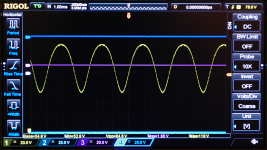
I had been working without an oscilloscope up till then. It was at this point that my then-new Rigol oscilloscope arrived, so I hooked it up to the anode of the 6AG5, and got my first look at what I had been hearing (pic attached.)
Looking at the 'scope trace, I was pretty shocked to see just how much even-harmonic distortion I had ended up with. With my little 2-watt amp, this sounds completely clean if you play a single note on the guitar. If you take away the treble boost EQ and play two bass notes at once, you can hear a little intermodulation distortion, too slight for most guitarists to notice, though anyone with Hi-Fi leanings will hear it immediately.
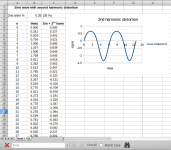
At the time I didn't realize there was an FFT function in my 'scope, so I fiddled with a spreadsheet and tried to duplicate the 'scope waveform by adding a second harmonic term to a sine wave. I came close with 35% (!!!) second harmonic (pic attached.)
Our ears get more sensitive at higher SPL levels, so maybe we don't need 35% second-harmonic distortion for good "tubey" cleans at higher SPL. But for a two-watt amp, and my ears, this turned out to be about right.
One of the things I would like to do with FETs is see if I can get anywhere close to this amount of second harmonic distortion. So far, I can only get there with some sort of subtractive circuit, in which I subtract a portion of the undistorted, phase-reversed input signal from the signal at the FET drain.
Anyway: here are (a) the anode waveform from the 6AG5 driving my phase inverter, and (b) the spreadsheet simulation of it.
-Gnobuddy
A couple of years ago I was fiddling around trying to make the clean tones from my little 6AK6 push-pull amp sound good. I was working with just the power amplifier section, which consisted of one (valve) gain stage, an LND150 source-o-dyne, and a pair of 6AK6 as outputs.
After a few failed experiments, I tried using a 6AG5 (small RF beam tetrode) as the gain stage, and immediately got better, more "valvey" cleans. They got better as the amp got louder, and the signal traversed a bigger region of the load-line.
So I added a pair of resistors to attenuate the signal between the 6AG5 and the LND150, so I could drive the 6AG5 a little harder for the same speaker volume. Bingo, better cleans again.
Adding a graphic EQ pedal and dialing in a smooth treble boost starting at about 1 kHz and rising gently to 5 kHz produced some really nice "tubey" cleans.
I had been working without an oscilloscope up till then. It was at this point that my then-new Rigol oscilloscope arrived, so I hooked it up to the anode of the 6AG5, and got my first look at what I had been hearing (pic attached.)
Looking at the 'scope trace, I was pretty shocked to see just how much even-harmonic distortion I had ended up with. With my little 2-watt amp, this sounds completely clean if you play a single note on the guitar. If you take away the treble boost EQ and play two bass notes at once, you can hear a little intermodulation distortion, too slight for most guitarists to notice, though anyone with Hi-Fi leanings will hear it immediately.
At the time I didn't realize there was an FFT function in my 'scope, so I fiddled with a spreadsheet and tried to duplicate the 'scope waveform by adding a second harmonic term to a sine wave. I came close with 35% (!!!) second harmonic (pic attached.)
Our ears get more sensitive at higher SPL levels, so maybe we don't need 35% second-harmonic distortion for good "tubey" cleans at higher SPL. But for a two-watt amp, and my ears, this turned out to be about right.
One of the things I would like to do with FETs is see if I can get anywhere close to this amount of second harmonic distortion. So far, I can only get there with some sort of subtractive circuit, in which I subtract a portion of the undistorted, phase-reversed input signal from the signal at the FET drain.
Anyway: here are (a) the anode waveform from the 6AG5 driving my phase inverter, and (b) the spreadsheet simulation of it.
-Gnobuddy
Attachments

Member
Joined 2009
Paid Member
There is quite a good chance it does!I would guess that the current SE amp I'm playing through looks about like that in the mid-high volume range.
In fact, the inspiration for trying the 6AG5 was the sound I'd heard from a Vibro Champ XD in a music store a few years previously.
The VCXD is (was!) a small cheap amp with a small cheap speaker and a small cheap enclosure, but the signature harmonic spectrum of a single-ended 6V6 still came through. It was the first time I'd heard that, and it left an impression. I could not get such lovely cleans out of my more expensive push-pull Super Champ XD, which was the only other "tube" amp I had any experience with at that time.
Later I found out the 6V6 was a beam tetrode, and that beam tetrodes tend to produce more second harmonic, and less third harmonic, than true pentodes like the EL84. I already knew that push-pull tended to cancel even harmonics, and now I had heard for myself the massive difference that this makes for clean tones.
(Speaking of true pentodes like the EL84, as it happens, I've never heard an EL84 amp I really liked. I'm not saying all EL84 amps are bad, of course, just that they don't ring any bells for my particular ear/brain combination - it's a matter of personal preference.)
So when I started to design my own little amp, I had already been thinking about the possibility of finding a small-signal beam tetrode, if such a thing existed, to see if I could capture some of the same magic as a single-ended 6V6 output stage.
All the reading I'd done up to that point suggested that beam tetrodes were only used in power stages, to compete with pentodes. In fact, they were usually called "beam power tubes", as though to highlight the fact that they only came in larger sizes, for use as power devices. And 99% of the time, I could only ever find references to 6L6, 6V6, KT88, and a tiny handful of other devices, all of them designed for power output.
Not knowing anything about the era of valve RF, it took me a lot of hunting before I stumbled across the fact that pentodes were not only good for audio power output, but also for RF. The much lower Miller capacitance made RF design hugely easier and more capable. This was true for both RF preamps and RF power amps, and that was one reason why there were lots of little small-signal RF pentodes manufactured at one time.
Since beam tetrodes also have low Miller capacitance, that immediately had me wondering if beam tetrodes had similarly been used for RF. I quickly found out that they had, but once again, all the references I turned up at first only talked about beam power tubes used for power (RF output stages).
But a lot more hunting finally turned up the fact that the tiny little 6AG5 "RF pentode" is actually a beam tetrode (though the datasheets all say "pentode"!)
So I tried one in my amp, hoping for some 6V6 family magic, and I was very pleased to find out that the 6AG5 delivered as hoped for. Lovely single-ended sound, without the usual single-ended amp headaches!
Since then I've realized that there are probably a lot of later-generation TV tubes (including a lot of triode-pentode tubes) that contain little beam tetrodes masquerading as pentodes.
I have found one other for certain, the 6JW8. I looked at one of mine with a magnifying lens, and you can see that there are only four grid support rods in the pentode section - only enough rods to support two grids, in other words, not three. So the "pentode" is really a beam tetrode in disguise.
-Gnobuddy
I did actually unbalance it, by 1 decibel (about 12%).If you unbalance the source-o-dyne with unequal resistors won't this give you a nice 2nd harmonic ?
That number was based on a 'Web page I found by another diyAudio member, Bob Roberts, who, as it turned out, had sat down with signal generators and spectrum analyzers to answer the same question I had in my head: "How much do we need to unbalance a push-pull amp to let the single-ended harmonics mostly come through?"
So I stole Bob's hard work, unbalanced my source-O-dyne by one decibel, and - nothing! It didn't really sound any more "tubey" or "valvey" to me!
I don't know why it didn't work. Maybe my output stage was already 1 dB out of balance by accident, and I ended up actually improving its balance. Maybe my little 6AK6 output valves weren't generating enough second-harmonic distortion for my tastes, at the lower SPL levels I was using. Maybe I wasn't driving them hard enough.
So at that point I began to think that that good clean tone from a push-pull amp would have to be generated earlier in the audio chain, not at the output stage.
You need a big signal swing to really expose a valve's non-linearity. So where would be the best place to generate that clean tone?
The largest signal in my amp (once you'd discarded the output) was at the source-o-dyne input. So I tried the 6AG5 as the stage driving it. And it worked!
In my amp, the 6AK6's are biased to -10 volts. They only need 20Vpp of drive to start to clip (and the 2-watt amp is too loud for home use at that point.) The source-o-dyne has unity gain to each output, so it also only needs about 20 Vpp of drive to start to clip the amp.
After I got my 'scope, I found out that the 6AG5 in my circuit, running centre-biased on about 150V B+, can put out about 120Vpp of signal before it begins to clip. Of course there is much more tasty second-harmonic distortion when it's putting out 120Vpp than when it's putting out 20Vpp.
So that's when I decided to try putting in roughly a 5:1 fixed voltage divider in between the 6AG5 and the source-o-dyne. That would still allow up to 24Vpp drive into the source-o-dyne, more than enough for clean tones. But the 6AG5 would be swinging through 25 Vpp even when I was only feeding 5Vpp to the source-o-dyne, enough so you could definitely hear that "valvey" sound most of us want in our guitar clean tone.
-Gnobuddy
If you unbalance the source-o-dyne with unequal resistors won't this give you a nice 2nd harmonic ? ...
*Only* if the two output devices individually have large even-order distortion.
Think. Say you had two dead-clean output tubes. Unbalance all you want; the output is dead clean.
For typical devices of ~~5% THD, cancelling to <0.5% even-order in push-pull, I'd expect to need a lot more than 10% unbalance to give "any" even-order distortion. 100% unbalance (one side dead) only gives the 5%.
Maybe the output of each tube would be dead clean but one half the waveform would be bigger than the other half of the waveform. I would think the signals would add up in Class A operation but once you get into Class B the one tube with more signal will clip sooner than the other. How much would you have to unbalance them to get an audible effect I do not know.
I did play with a paraphase splitter in one amp and adjusted the balance on the scope. Then I played around by ear adjusting the balance with different signal levels. I found I liked quite a bit of unbalance when playing the amp 'clean' but when rocking out it seemed like the sound went to mush and the amp sounded better when the splitter was set for equal level to each output tube.
I did play with a paraphase splitter in one amp and adjusted the balance on the scope. Then I played around by ear adjusting the balance with different signal levels. I found I liked quite a bit of unbalance when playing the amp 'clean' but when rocking out it seemed like the sound went to mush and the amp sounded better when the splitter was set for equal level to each output tube.
I have come to the same conclusion: lots of low-order even harmonic distortion for good cleans, lots of low-order odd-harmonic distortion for good overdrive....I liked quite a bit of unbalance when playing the amp 'clean' but when rocking out...the amp sounded better when the splitter was set for equal level to each output tube.
There is other stuff too, of course, in particular, managing intermodulation distortion and/or using EQ to emphasize some frequency ranges.
I think this is where grid current flow and the resulting bias shifts can be used to advantage. Have the operating point shift with increasing overdrive, so the harmonic spectrum shifts from mostly even-harmonic towards mostly odd-harmonic.
Warm-biasing a gain stage, and letting it bias itself colder, towards mid-bias and symmetrical clipping, as signal levels go up, is probably one way to achieve this.
-Gnobuddy
This is a follow-up to this previous post.<snip>
35% (!!!) second harmonic
<snip>
One of the things I would like to do with FETs is see if I can get anywhere close to this amount of second harmonic distortion.
KMG seems to have pretty much nailed triode emulation using FETs. So what's left for us lesser mortals to do?
Well, how about trying to emulate the output of a single-ended beam tetrode (not a triode) with an FET? Many blues players love single-ended amps with a 6V6 or 6L6 at the output. Can we make an FET sound a bit like that?
As mentioned in the bit of my old post that I quoted above, it is hard to extract 35% second harmonic from an FET. Every simple FET circuit I tried so far will clip long before it generates 35% second harmonic. Beam tetrodes, though, will happily generate 35% (mostly) second harmonic distortion well before clipping, as my little 6AG5 did, or Michael Koster's single-ended 6L6 probably does.
So what shall we do if we'd like an FET to sound more like a single-ended 6V6 or 6L6 or 6AG5?
I mentioned this earlier, but didn't explain what I meant, so it may have gone unnoticed.So far, I can only get there with some sort of subtractive circuit, in which I subtract a portion of the undistorted, phase-reversed input signal from the signal at the FET drain.
In a nutshell, I found a technique that lets one increase the amount of distortion from an FET beyond the limitations of the device itself.
The idea is based on the mathematics of distortion: an FET's transfer function can be mathematically written as a linear term plus a quadratic (squared) term. Fed a sine wave, the second harmonic distortion is generated by the quadratic term. The undistorted part of the output signal (at the same frequency as the input) is generated by the linear term.
So the percentage of second harmonic distortion is set by the ratio of the quadratic term to the linear term. Unfortunately, this is baked into the FET transfer function; we can't change it much (maybe a wee bit by choice of operating point.)
But what if we take a part of the input signal, amplify it linearly, and subtract this from the signal coming out of the FET?
This partially cancels, and so reduces, the size of the linear, undistorted signal from the FET (i.e. effectively reduces the linear term in the FET transfer function.)
But a linear term cannot cancel a quadratic term, so the second harmonic part of the signal is left unchanged.
This means we have now increased the percentage of second-harmonic distortion in our summed signal, at the cost of some lost gain, since we've cancelled out part of our linearly amplified signal.
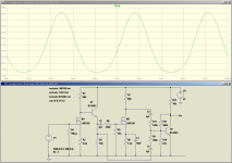
I'm attaching below the 6AG5 "clean tone" 'scope trace as a reminder of what we want from the FET, and an LTSpice screenshot of a circuit I devised to exaggerate FET second harmonic distortion as outlined above.
Resistors R9 and R11 mix the linear and distorted signals together in the active mixer (Q2). The two signals are not equal in size (due to the gain of M2 and the attenuation in R8/R5), nor do we want them to cancel completely (this would completely cancel the fundamental and leave you with a very small, frequency-doubled output. Maybe good for octave effects.)
What comes out of the circuit after this subtraction process is amplified a little bit by Q2, and as you can see, the simulated waveform now has about the right level of second harmonic distortion to come close to the real thing (a single-ended beam tetrode.) Reducing R9 dials up the distortion; increasing it dials it down. In practice, R9 should be a pot, or at least a trimpot, to allow dialing in the proper sound.
The output of my circuit is inverted compared to the single-ended 6AG5 - that's because of the inverting mixer stage in my circuit. Inverting the entire audio signal doesn't change the percentage distortion, or the sound of the signal.
Real beam tetrodes in SE circuits seem to produce audible amounts of 3rd and maybe 4th harmonic distortion. I don't think FETs do. So I don't expect this FET circuit to sound identical to the 6AG5 in my amp.
I haven't built this circuit (yet), but I think it's worth trying. If we're lucky, it will produce good clean tones that at least loosely resemble a single-ended amp with a beam tetrode output. If we're very lucky, it may also turn out to overdrive in a musically usable way.
And if we're not lucky - well, there is, of course, always the possibility that it will not sound good at all!
-Gnobuddy
Attachments
But what if we take a part of the input signal, amplify it linearly, and subtract this from the signal coming out of the FET?
Reminiscent of Bob Cordell's distortion magnifier and similar circuits, but for a very different purpose, of course. Cool.
This is a follow-up to this previous post.
KMG seems to have pretty much nailed triode emulation using FETs. So what's left for us lesser mortals to do?
-Gnobuddy
I think getting 30V Fets to work would be a challenge enough.
- Status
- This old topic is closed. If you want to reopen this topic, contact a moderator using the "Report Post" button.
- Home
- Live Sound
- Instruments and Amps
- Tube Emulation & EQ