After some poking through an old tube manual I realized that the other "FM radio" tube I was thinking of was not a tuner tube. It was the 6T8, a 6AL5, and a 6AT6 in one bottle. Developed exclusively for FM radio, the twin diode was the FM demodulator and the 6AT6 (triode / diode) was the AM demodulator and first audio amp.
The same book (RCA RC30) informed me that the 6DT8 IS a 12AT7 with a shield added between the sections. This eliminated the heater tap, so both 6 and 12 volt versions were made.
The same book (RCA RC30) informed me that the 6DT8 IS a 12AT7 with a shield added between the sections. This eliminated the heater tap, so both 6 and 12 volt versions were made.
So we have ended up with a range of "maximum peak guitar signal voltage" measurements that span a rather extraordinarily large range of 54 dB.
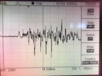
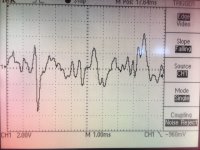
Here is an observation, easily repeatable, that confirms the upper end voltage output by an electric guitar to be in the neighborhood of 10V peak to peak.
The guitar is loaded with about 1M ohm and 420pf, which is very close to the load using my 6 foot low capacitance cable (300pf) into a typical 12AX7 gain stage (1.7pF Cag * 60 Av + ~15pf input capacitance).
There is no "club hand" drama or windmill action involved in the technique needed to evoke this signal level; rather it is more of a rotation of the lower arm from the elbow through the wrist, which pivots the plectrum through a short arc at high velocity... I liken it to the martial arts trick of slamming the book into the shelf from 1/4 inch away by flicking the fist from the wrist...
I get this playing something like the intro to "Just What I Needed" by The Cars where there are some muted staccato chords and explosive bar chords in contrast. tut - tut - tut - tut - tut - tut- tut - tut - BAH - BAH - tut - tut...
... so at what voltage level should the amp do its nasty clipping?
Cheers!
PS The rig is a $300 parts-built guitar from guitarfetish.com with the hottest pickups I could find, about 15K bridge and 11K neck, both pickups on, controls full CW, coil taps out (full coils). The guitar has 1M pots as well.
PPS similar experiments with vintage tube microphones show similar tendencies; they can deliver about as much signal voltage as the circuit is capable of producing (e.g. several volts peak-peak from a Neumann U-67 with the pad switched out). Another place where you realize there is some inevitable limiting in the mic itself (unless it is a DPA mic with the 130V supply...) which could be why tube mics sound better on a lot of source material. And it's not vocal screamers but rather things like bells that will generate the big signal transients.
Attachments
Last edited:
Turns out it's ~13K bridge pickup and 9K neck pickup. I was thinking about the DiMarzio "Sonic Ecstasy". These are more like the "Super Distortion" line....hottest pickups I could find...
Also string gauges are sort of "power slinky + heavy bottom", like .011/.014/.018/.030/.042/.052
Last edited:
(Note to myself: Do NOT tick Michael Koster off!)I liken it to the martial arts trick of slamming the book into the shelf from 1/4 inch away by flicking the fist from the wrist...
Thank you very much for making those measurements!
Some day in the future I will finally be done with this amp, and one of the things I'd like to do then is repeat your measurement - except using my old Squier Standard Stratocaster, and, of course, with me doing the playing.
The Squier Standard has very low-output pickups, and I think I come closer to the butterfly-wing picking technique than the karate-chop through four blocks of ice picking technique.
")
I have heard the input of my Princeton Reverb overload just from strumming chords on my old Ibanez AS73 semi-hollow (with stock pickups). I guess Leo didn't anticipate some future developments in both ceramic magnets and guitar pickup design.... so at what voltage level should the amp do its nasty clipping?
I am still inclined to believe that your 10V peaks are several standard deviations away from the mean "biggest peak guitar signal" that most people generate with their guitars.
-Gnobuddy
At last week's jam, my friend (the guy I'm planning to give this amp to as a gift) started talking about being worried that he was inconveniencing me, because I've been lending him my Super Champ XD to use for some time now.
I did my best to reassure him, but I'm worried he's going to go off and buy something off Craigslist any day now. Not only does he not need the unnecessary expense, but on his budget, he is also unlikely to get anything that sounds as good as the one I'm building for him.
So I made a push these last few days to get this project completed far enough so I can give it to my friend a couple of days from now, at this week's jam. It won't be finished, but the idea is to get it playable, and basically say "This is for you, it will be finished soon, but you can play through it today."
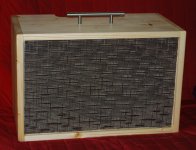
I won't bore you with the details, but the grille is on, and the de-nastification filter and class-D power amp are connected up and working. No control panel yet, but the class-D module has its own input level control, which can temporarily be used as a volume control.
There is some cosmetic stuff left to do as well - some sort of trim to cover the edge of the grille where it meets the wood, and the outer back panel to cover the electronics.
I don't really like giving someone a half-baked amp and having to take it back to finish it, but I don't think I have a choice, given the circumstances.
Let's hope he hasn't already bought an amp!
The photo doesn't get the colours quite right, but at least you can get a ballpark idea of the amps current appearance.
-Gnobuddy
I did my best to reassure him, but I'm worried he's going to go off and buy something off Craigslist any day now. Not only does he not need the unnecessary expense, but on his budget, he is also unlikely to get anything that sounds as good as the one I'm building for him.
So I made a push these last few days to get this project completed far enough so I can give it to my friend a couple of days from now, at this week's jam. It won't be finished, but the idea is to get it playable, and basically say "This is for you, it will be finished soon, but you can play through it today."
I won't bore you with the details, but the grille is on, and the de-nastification filter and class-D power amp are connected up and working. No control panel yet, but the class-D module has its own input level control, which can temporarily be used as a volume control.
There is some cosmetic stuff left to do as well - some sort of trim to cover the edge of the grille where it meets the wood, and the outer back panel to cover the electronics.
I don't really like giving someone a half-baked amp and having to take it back to finish it, but I don't think I have a choice, given the circumstances.
Let's hope he hasn't already bought an amp!
The photo doesn't get the colours quite right, but at least you can get a ballpark idea of the amps current appearance.
-Gnobuddy
Attachments
I built and tested the active tilt control. After a short test, I really like it. I had been concerned that there wouldn't be enough flexibility without independent treble and bass controls, but in practice I didn't find that to be the case.
For the intended owner, it is a definite advantage, as he doesn't get along well with complex gadgets.
Remember: this tilt control works in conjunction with a "de-nastifying filter" which includes an 800 Hz notch, treble roll-off above 2 kHz, and a little bass lift below about 400 Hz. All that stuff is on a separate PCB (and a separate schematic). I don't know how the tilt control would sound on its own - not as good, I think.
I decided to just use another piece of proto-board, and AC couple where necessary, rather than mess around with the minimal-components version of the circuit I posted a few days ago. So I changed a few things in the circuit.
An LTSpice screenshot showing the correct schematic is attached. Component values are the same as the ones in my real circuit, but the MPF102 model in LTSpice doesn't bias up the same way as my real MPF102's do.
In real life, both MPF102s are biased to have half B+ at the drain. The BC550C emitter follower also biases to half B+, this time at the emitter.
I love this family of little silicon small-signal transistors, descendants of the wonderful BC148 / BC158 I grew up with. Extraordinary current gain, virtually ideal characteristics, and cheap, too.
When's the last time you saw a 3.9 megohm bias resistor in a transistor circuit? I calculated that value assuming a beta of about 500, and the BC550C I stuck in my breadboard met that spec, biasing up neatly to almost exactly half B+ at the emitter.
I'm home sick with the 'flu today, so I have to miss tonight's jam. My wife is going, though, and she's going to present the amp to our friend. Fingers crossed all goes well...the amp still has guts hanging out the back, held in place with masking tape!
-Gnobuddy
Attachments
6DT8 sure looks like 12AT7 except the heater-tap pin became a shield pin.
The RCA RC-30 tube manual says:
Type 12DT8 is identical with type 6DT8 except for the heater ratings. GT
Except for heater and heater-cathode ratings, inter- PT electrode capacitances, and basing arrangement, these 9AJ types are identical with miniature type 12AT7.
6AQ8 has a longer "tail" than 12AT7.....I abused them in a headphone amp. Worked real good for about 6 months.
Did the tubes die, or were they changed for another reason? The 5 tube screamer that I built with 26AQ8's became horribly microphonic from playing it with the bare board sitting on top of the speaker cabinet. That version was wired for a series string heater system operating from the B+. There is no 150 mA version of the 6CW5, so I can't simply stuff 12AX7's (7025's) in it.
voltage output by an electric guitar to be in the neighborhood of 10V peak to peak.
I'll see how much voltage I can make with some of my old guitars.
And it's not vocal screamers but rather things like bells that will generate the big signal transients.
Mic'ing one of my Turbo Champs with an SM57 back in the late 90's generated more voltage than any of the band kids hanging out at my house could scream (oh I mean sing). Cymbals did too........note from my past....never put the SM57 INSIDE the bass drum! My daughter played drums back then and I did a lot of experimental recording with the then state of the art 44/16 cards.
Anyone remember the Pro Audio Spectrum card running on Windows 95 or 98 with Cakewalk Pro Audio software? Pretty powerful stuff in the 90's, a killer DAW later on, now dead due to cost cutting by Gibson late last year.
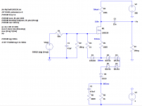
While I'm waiting for the LND150s and schottky diodes to arrive, I decided to fire up LTspice and simulate the 1st stage of KMG's JCM800 preamp.
http://milas.spb.ru/~kmg/files/projects/jcm800mv/fet/lnd150/jcm800mvfSch.pdf
I used the LND150 spice model posted earlier in this thread. Had to use a couple of substitutions for diodes, but should be close enough.
A couple of observations:
Now I've been wondering what is the purpose of the schottkys. At first, I thought it had to do with the grid current simulation that results in the bottom of the output waveform being rounded off. However, after simulating the circuit without the schottkys, I found this is not really the case.
The grid current is simulated by the diode from gate to source resistor. This will achieve the rounding off of the bottom. In fact, even a diode from gate to ground will do the same. This trick is used with Jfets in some of the RunoffGroove projects.
After an A/B inspection of waveforms with schottkys and without schottkys, I found the schottkys actually affect the top of the waveform. Without the schottkys, the top clips sharply. With the schottkys, there is some rounding off, and a more gradual cutoff, similar to how the 12AX7 has its characteristic plate curves "bunched up" near cutoff.
I'm not exactly sure how this works.
Perhaps if you think of the schottkys as something like "voltage controlled variable resistors", they are not a switch, they don't immediately go from passing no current to passing everything.
KMG says the high voltage fast-recovery diode is there to protect the BAT54 schottkys.
I'm not sure how that would protect them, but I'll take his word for it. I notice he does not use protection zeners on the gate of the LND150.
The next thing is why the negative supply?
Well, at B+ of 280v and 100k drain resistor, the LND150 needs about 500mv Vgs.
Since the gate is tied to ground, you can't have 4 schottkys, a silicon diode and two resistors in the source circuit chain without tying it to a negative supply.
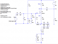
But there's another option.
Tie the source circuit to ground and make the gate more positive than ground. This is the "fixed bias" approach, rather than "self bias".
This involves setting up a voltage divider from B+ to ground, and tying the 1Meg gate resistor to the voltage divider instead of ground. Also, you have to capacitively couple the input signal to the gate.
So I simulated it.
After fudging around with the resistors in the voltage divider, I was able to get the LND150 to bias up reasonably close to its "self bias" mode.
Then I ran the simulation and got 99% the exact same output waveform.
When I get the parts and build the actual circuit, I will try the fixed bias approach, thus avoiding the need for a negative supply.
Although I prefer the self bias approach for Jfets, this is not a Jfet, and I think fixed bias is a legitimate choice here.
Am also thinking of building the Gnobuddy "de-nastifier" circuit in high voltage using LND150 as source followers, may need to scale up some resistor values. This way, would only need one power supply. This could be based on a cheap "international travel" transformer, which should provide around 300v after rectifying.
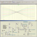
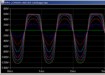
I have attached the 1st stage with negative supply (self bias), output waveform with input signal stepped from 0 to 4v at 500mv intervals, and the 1st stage fixed bias. The output waveform for this is nearly identical to the self biased circuit,
http://milas.spb.ru/~kmg/files/projects/jcm800mv/fet/lnd150/jcm800mvfSch.pdf
I used the LND150 spice model posted earlier in this thread. Had to use a couple of substitutions for diodes, but should be close enough.
A couple of observations:
- LND150 is both depletion and enhancement mode, unlike a Jfet.
- The simulated drain voltage exactly matches the voltage on KMG's schematic. So the spice model is pretty good, at least for static DC operating point.
- The nominal stage gain is around 50, about the same as the 12AX7 in the 1st stage of the actual Marshall amp.
- There is some low frequency rolloff, as in the actual amp.
- When overdriven, the bottom of the output waveform is very rounded off, and the top clips to a flatline, but is slightly rounded at the corners, very similar to 12AX7.
Now I've been wondering what is the purpose of the schottkys. At first, I thought it had to do with the grid current simulation that results in the bottom of the output waveform being rounded off. However, after simulating the circuit without the schottkys, I found this is not really the case.
The grid current is simulated by the diode from gate to source resistor. This will achieve the rounding off of the bottom. In fact, even a diode from gate to ground will do the same. This trick is used with Jfets in some of the RunoffGroove projects.
After an A/B inspection of waveforms with schottkys and without schottkys, I found the schottkys actually affect the top of the waveform. Without the schottkys, the top clips sharply. With the schottkys, there is some rounding off, and a more gradual cutoff, similar to how the 12AX7 has its characteristic plate curves "bunched up" near cutoff.
I'm not exactly sure how this works.
Perhaps if you think of the schottkys as something like "voltage controlled variable resistors", they are not a switch, they don't immediately go from passing no current to passing everything.
KMG says the high voltage fast-recovery diode is there to protect the BAT54 schottkys.
I'm not sure how that would protect them, but I'll take his word for it. I notice he does not use protection zeners on the gate of the LND150.
The next thing is why the negative supply?
Well, at B+ of 280v and 100k drain resistor, the LND150 needs about 500mv Vgs.
Since the gate is tied to ground, you can't have 4 schottkys, a silicon diode and two resistors in the source circuit chain without tying it to a negative supply.
But there's another option.
Tie the source circuit to ground and make the gate more positive than ground. This is the "fixed bias" approach, rather than "self bias".
This involves setting up a voltage divider from B+ to ground, and tying the 1Meg gate resistor to the voltage divider instead of ground. Also, you have to capacitively couple the input signal to the gate.
So I simulated it.
After fudging around with the resistors in the voltage divider, I was able to get the LND150 to bias up reasonably close to its "self bias" mode.
Then I ran the simulation and got 99% the exact same output waveform.
When I get the parts and build the actual circuit, I will try the fixed bias approach, thus avoiding the need for a negative supply.
Although I prefer the self bias approach for Jfets, this is not a Jfet, and I think fixed bias is a legitimate choice here.
Am also thinking of building the Gnobuddy "de-nastifier" circuit in high voltage using LND150 as source followers, may need to scale up some resistor values. This way, would only need one power supply. This could be based on a cheap "international travel" transformer, which should provide around 300v after rectifying.
I have attached the 1st stage with negative supply (self bias), output waveform with input signal stepped from 0 to 4v at 500mv intervals, and the 1st stage fixed bias. The output waveform for this is nearly identical to the self biased circuit,
Attachments
This could be based on a cheap "international travel" transformer, which should provide around 300v after rectifying.
A true transformer or an autotransformer?
That made me do a slight double-take the first time I saw the LND150 datasheet. So Vgs can be negative, positive, or zero, depending on Idss, and how much Id you decide to bias it for.LND150 is both depletion and enhancement mode, unlike a Jfet.
After an A/B inspection of waveforms with schottkys and without schottkys, I found the schottkys actually affect the top of the waveform. Without the schottkys, the top clips sharply. With the schottkys, there is some rounding off, and a more gradual cutoff, similar to how the 12AX7 has its characteristic plate curves "bunched up" near cutoff.
I have seen (old) audio circuits that actually used silicon diodes as voltage controlled variable resistors. The Phillips Dynamic Noise Reduction circuit (a pre-Dolby way to reduce cassette playback hiss) was one.Perhaps if you think of the schottkys as something like "voltage controlled variable resistors",
If you differentiate the Shockley diode equation and do a little algebra, you come up with the interesting result that the small-signal resistance of a diode equals (26/Id), where the resistance is in ohms, and Id is the diode current in milliamps.
In other words, the dynamic resistance of an ordinary silicon diode is 26 ohms at 1 mA, 52 ohms at 0.5 mA, 260 ohms at 0.1 mA, and so on.
Things seem to be considerably more complicated for Schottky diodes ( Schottky diode current ), but they too have a dynamic resistance that rises as the current through them falls.
In KMG's circuit, you can see how the increasing dynamic resistance of the diodes would progressively reduce the effective transconductance of the LND150 as the current through it falls, rounding off the tops of the waveforms as you described. As you say, like a variable external source resistor.
I've been curious about that as well. The LND150 datasheet specifies a maximum of +/- 20 volts between gate and source.I notice he does not use protection zeners on the gate of the LND150.
If I read the datasheet correctly, it also says there are no internal diodes to limit gate-source voltage to a safe value. My guess is that this is exactly for the reason you mentioned before: because Vgs can legitimately go either positive or negative, so a single diode cannot provide protection and allow normal operation.
In my LND150 "sourceodyne" phase splitter, I used two series-connected, back-to-back, 12V zener diodes between gate and source, which work in conjunction with a 47k "gate stopper" resistor. That circuit (running on 150V DC) has been trouble-free since I built it a couple of years ago now.
Anecdotally, there are several DIY tales on the 'Net of blown LND150s that died due to lack of external gate protection. But it's hard to pin down exactly what went wrong in most cases.
It may be that KMG's input diode clamp never lets the gate go above +0.7 volts or so, while his diodes in the source circuit prevent any reverse current ever flowing into the source when the gate is below source voltage, and that these two effects combine to allow the LND150 to survive without additional gate protection.
It still bothers me that there appears to be nothing to limit reverse voltage between gate and source - only to limit reverse current between gate and source. As I understand it, by the time any kind of current starts to flow into a MOSFET gate, it's too late - the delicate gate insulation barrier has been blown permanently.
Congratulations! Very interesting! Great work!..."self bias" mode.
Then I ran the simulation and got 99% the exact same output waveform.
Some months ago I tried to do the same thing in LTSpice, but my simulations didn't work properly at all. Without the negative supply, I had to use an input coupling cap, and the input coupling cap would charge up through KMGs "grid current" clamp diode, screw up the DC bias voltage on the gate, and the LND150 would shift towards cutoff. And then nothing worked the way it was supposed to according to KMG's oscilloscope photos.
I'm at work now, but after I get home, I'll see if I can find my failed simulations, and compare them with your successful ones, to see if I can figure out what I did wrong.
Funnily enough, I was thinking about building a little circuit to knock down big (triode level) AC signals to instrument level, buffer, feed into my trusty Danelectro Fish-n-Chips EQ pedal, then re-amplify back to original signal level. Sorta like a portable FX loop with only one pedal in it.Am also thinking of building the Gnobuddy "de-nastifier" circuit in high voltage using LND150 as source followers
That would let me insert the Fish-n-Chips between stages in a proper "toob" guitar amp without frying it, so it could be used to quickly find the proper EQ for maximum de-nastifying effectiveness.
I still don't know why the particular EQ curve I locked into my de-nastifying filter worked so well to "de-nastify" my amp, nor do I know whether that particular curve is more or less universal, or whether a very different amp or guitar might demand a very different curve. Hence my tendency to hedge my bets by continuing to use the Fish-n-Chips for voicing, until maybe time and experience allows a more definite conclusion about the optimum de-nastification curve.
That sounds like a plan!This could be based on a cheap "international travel" transformer, which should provide around 300v after rectifying.
An alternative approach is to just voltage-double the output of a normal 120V:120V isolation transformer, which should get you somewhere in the 330V - 350V DC range, depending on the transformer. A Triad N-48X is only $14.10 USD at Mouser.com, and good for 15 watts.
As I mentioned earlier, I like voltage doublers, I think they can be very elegant solutions that let us use today's off-the-shelf transformers and still come up with the high voltages we need for valves (or, in this case, for KMG's pretend-valves!)
-Gnobuddy
Most of the ones I've seen lately are too small and light to contain an actual 60 Hz (or 50 Hz) transformer.A true transformer or an autotransformer?
I'm not sure how they work, but my guess is they are actually a high frequency switching boost converter of some sort that spits out a crude square-wave approximation to whatever international wall voltage it's supposed to mimic.
There have been a few threads and posts about using a car inverter to generate HV for valves from a 12V DC power source. If you use a 230V automotive inverter, there is an internal DC supply rail somewhere north of 300V that you can tap into. Relatively high power (100W and more) is easily available.
But some internal modifications are necessary, and those are teensy SMD parts we're talking about.
Those 390V boost-converters from Amazon look hard to beat for convenience and cost, if you don't need 100 W capability.
-Gnobuddy
A true transformer or an autotransformer?
Oh, are those things autotransformers? Well that won't do. Thanks for the heads up.
Ok, a cheap isolation transformer from Mouser or digikey, such as Triad N68X, about $16.40
It says 115/230 "primary", 115 "secondary", but it's an isolation transformer, primary and secondary are kind of arbitrary.
Actually I can make a step up "isolation" transformer out of two "wall wart" transformers. I've got a big box of old wall warts, the old non-switching kind. So the transformers from a 6V and 12V ought to do it. I can just cut the transformers out of the plastic cases and discard the rectifiers and stuff. We're only talking about a few milliamps load, so should not be a problem.
For prototyping purposes I'll use the Hammond iron I mentioned previously.
It says 115/230 "primary", 115 "secondary", but it's an isolation transformer, primary and secondary are kind of arbitrary.
The windings do not have exactly the same number of turns. The "secondary" has a few extra turns to make up for the core and resistive loss. Running them backwards still works, you will just get a few volts less than expected. I get a B+ voltage of about 170 volts when operated as intended, and +/- 165 volts when reversed.
For small applications (powering HV mosfets in tube amps) I use the Hammond 229B230 or the Triad FP230-50. They are small and PC board mountable. The transformer, 4 diodes and two caps for +/- 170 volts fit on a 2.5 X 3 inch PC or perf board. Both transformers have the same footprint, and can be obtained from Mouser.
I guess there's nothing new under the sun. Looks like the schottkys need to be in the circuit to do this right. Now we have a better understanding why.I have seen (old) audio circuits that actually used silicon diodes as voltage controlled variable resistors. The Phillips Dynamic Noise Reduction circuit (a pre-Dolby way to reduce cassette playback hiss) was one.
Yes, I think that is so. Obviously KMG put a lot of work into this and certainly he's aware of the problem, and didn't deem it necessary for any further gate protection.It may be that KMG's input diode clamp never lets the gate go above +0.7 volts or so, while his diodes in the source circuit prevent any reverse current ever flowing into the source when the gate is below source voltage, and that these two effects combine to allow the LND150 to survive without additional gate protection.
I wish I had the chops to come up with a different way of doing this and not have to blatantly copy KMG's work, but he really nailed it, and my time is limited.
Been through hell lately with kernel patches for this stupid Meltdown/Spectre thing. Messed up some Ubuntu servers I manage, as well as my boss's Ubuntu desktop box. They pushed out a kernel update that broke VirtualBox and we live and die on VirtualBox.
A couple of Windows boxes started running like molasses in January and others were fine.
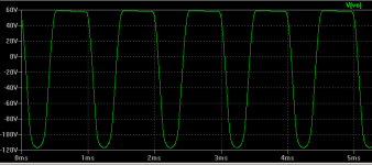
I re-ran the simulation, this time with a 4v signal, "time to start saving data" = 5000ms (5 sec). "stop time" = 5010ms.Some months ago I tried to do the same thing in LTSpice, but my simulations didn't work properly at all. Without the negative supply, I had to use an input coupling cap, and the input coupling cap would charge up through KMGs "grid current" clamp diode, screw up the DC bias voltage on the gate, and the LND150 would shift towards cutoff. And then nothing worked the way it was supposed to according to KMG's oscilloscope photos.
So it should simulate signal being applied for 5 sec, then start collecting data, and run for 10ms more.
The output looked good to me. see attached. I could be missing something though.
It's not the end of the world to generate -3v, whatever needs to be done.
Good idea, even cheaper than the N-68X, I like it.An alternative approach is to just voltage-double the output of a normal 120V:120V isolation transformer, which should get you somewhere in the 330V - 350V DC range, depending on the transformer. A Triad N-48X is only $14.10 USD at Mouser.com, and good for 15 watts.
I just got another crazy idea.
Let's say we do need -3v because of coupling cap charging issues.
Say we have 300VDC, from whatever source.
What if we leave that supply "floating", set up a series regulator with say IRF820, to deliver +3V.
So now we have +300, +3 and +0 volts.
Now we call that "+3V" point "ground".
So now we would have +297, 0, and -3 volts.
Is that feasible or am I just totally losing it?
Attachments
The windings do not have exactly the same number of turns. The "secondary" has a few extra turns to make up for the core and resistive loss. Running them backwards still works, you will just get a few volts less than expected. I get a B+ voltage of about 170 volts when operated as intended, and +/- 165 volts when reversed.
For small applications (powering HV mosfets in tube amps) I use the Hammond 229B230 or the Triad FP230-50. They are small and PC board mountable. The transformer, 4 diodes and two caps for +/- 170 volts fit on a 2.5 X 3 inch PC or perf board. Both transformers have the same footprint, and can be obtained from Mouser.
Thanks.
Never knew that about isolation transformers, make sense. Learn something new everyday.
What kind of things are you doing with mosfets in tube amps?
I picked up a couple of the travel transformers only to be disappointed when they got here.
I was thinking about why you can not float the 300V but never gave it enough thought as I am spending most of my time whittling wood. I just can not finish one guitar when I already have another started. I really wanted to play with some electronics, keep putting it off after I finish, this one.
I was thinking about why you can not float the 300V but never gave it enough thought as I am spending most of my time whittling wood. I just can not finish one guitar when I already have another started. I really wanted to play with some electronics, keep putting it off after I finish, this one.
I use a Hammond isolation transformer for a variety of voltages. The one I bought had a pair of input windings and 120V out but in Hammond speak that is more like 130V. I flipped the transformer around and used the two primaries in series as a secondary. Then also with them in parallel backwards. Doubled it the proper direction and backwards. All kinds of fun.Thanks.
Never knew that about isolation transformers, make sense. Learn something new everyday.
What kind of things are you doing with mosfets in tube amps?
- Status
- This old topic is closed. If you want to reopen this topic, contact a moderator using the "Report Post" button.
- Home
- Live Sound
- Instruments and Amps
- Tube Emulation & EQ