I need help with a couple of things with a small vintage tube amp.
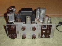
I just aquired a PA amplifier from a, circa 1958, Kodak Pageant film projector. I wouldn't be surprised if it's from model number AV-154, though I'm not entirely sure.
It's a cute little 15w amp with 2x 6l6 in push-pull with a single 12ax7 serving as a pre-amp and another 12ax7 serving as a phase inverter. I'm going to make it into a guitar amplifier and modify it slightly in the process.
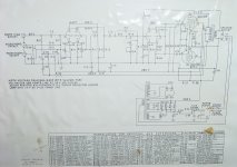
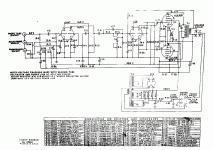
Here is the schematic, thankfully still intact on the bottom plate after all these years:
Kodak Pageant AV-154 Amp - Album on Imgur
Some socket/plug quirks that bear mentioning:
1) The speaker socket has a fail-safe for the mains. If the speaker plug isn't inserted, it won't turn on. I'm going to completely replace the speaker socket with a 1/4" jack.
2) The power socket was originally both a 117V connection to power the amp and a power connection to the film sound lamp (that reads sound info from film). Now the power socket is just connected to an AC cord.
3) The Photo Tube socket on the input is an RCA connector that would recieve sound from the film projector. I'm unsure if it would supply any voltage into the circuit but the amp works without it.
I'm a little out of my depths with this thing because, despite being able to figure most stuff out on my own, I'm far from being an expert in tube amplifiers and I need help with 2 things that I think are connected:
1) Are the 6L6 tubes fixed bias or cathode biased?
2) What part of the input circuit could be safely removed/simplified?
I'm planning to strip the input section to just one 1/4" jack and I'm having a hard time figuring out what can be safely removed. I'm looking at everything between the Microphone/Phonograph/Photo tube socket and pin 2 of the pre-amp tube as suspect for removal/replacement with a simple grid stopper resistor.
I'm having a hard time figuring out how the 6L6 tubes are biased, based on the schematic. I'm not sure but I think the photo tube socket was acting as a 60v bias tap for the 6L6 tubes for fixed bias or if they are cathode biased.
The amp works despite no connection on the photo tube socket.
Again: out of my depth, sure, but willing to learn.
I don't have a bias probe right now (on the way in the mail) or connected a 1ohm resistor in series with pin 8 of the 6L6 sockets to check bias voltage yet.
Can someone help me out on this?
Last edited:
Your schematic link doesn't open. But regardless of the type of 6L6 bias, why not assume the projector was made correctly, and whatever bias it has was correct for the circuit? After all the projector worked for how many years?
We can't answer the other questions without the schematic.
We can't answer the other questions without the schematic.
Sorry about that, here are the pictures/schematic:


and link to Imgur copy, just in case: Kodak Pageant AV-154 Amp - Album on Imgur
The bias circuit is confusing to decipher, which is why I'm asking for help.


and link to Imgur copy, just in case: Kodak Pageant AV-154 Amp - Album on Imgur
The bias circuit is confusing to decipher, which is why I'm asking for help.
Last edited:
Seems that the key to understanding this is to follow the common wire for
R27, R28, R29, and the secondary of the output transformer back to the
preamp and notice that it is grounded. Then:
R27, R28 are grid leak resistors keeping them at 0V for bias
R29 is self bias for the outputs, current causes a voltage drop making the
cathode positive and therefore the grids negative re the cathode.
Standard self bias.
Thanks PB2!
The line connecting R-36, R-4 and C-20 to the 6L6 cathodes was confusing me since that part of the input circuit was separated from the Mic and Phono inputs and I had no idea what purpose they were serving.
So would anyone have any comments about just gutting the input section (removing R1-8, R34-36, C-2, C-19 & C-20) and replacing it with the standard 1Meg to ground and 68k input resistor as used in damn near all guitar amps?
Or would that be a bad idea in some way?
Self-bias (and who cares?).
Don't put your finger in the photo-tube hole. It is not dangerous but will hum LOUD.
Adapt your guitar into either Phonograph or Microphone. They are very similar flat high-gain inputs. No further circuit changes needed to rock-out (since you have sorted the speaker and power interlocks).
Best S/N is with Mike/Phono full up and play loudness set with master Volume control. However other settings may be interesting.
This is not "any classic guitar amp" but may be a fine player even without a famous parent. (Anyway Kodak is more known in more lands than Fender; just not for guitars.)
The 60V for Photo is dropped from +220V by R3 and other parts. Yes, it does seem to return to 6L6 cathode bias resistor, but is not part of how the 6L6es bias. It is an odd detail; maybe they got more filtering or lower cost this way. Ignore it.
Attachments
Thanks PRR!
I did, however, ignore your advice about ignoring the extra filtering/voltage drop and just gutted the input section. These are just the first mods I'm doing to this amp.
The Kodak now has way more volume/gain available on tap. When the extra input circuitry was present, I had to have the microphone pot all the way up and only about halfway up on the main volume did I hear anything from a guitar plugged into the microphone input.
Now with a 33k resistor in series with the grid of the tube (didn't have a 68k), along with a paralell 1meg resistor to ground, I start hearing the guitar right away on the volume knob... and it just goes up from there. It's too late to see how it responds with even more gain but I'll see how it behaves tomorrow.
P.s. Yes, I realize that I might have loaded even more voltage to the pre-amp tube, but I figured that a jump from 160v to a possible 220+v should be within spec of a 12ax7.
Nothing blew up so far
Good day! I was given a Kodak Pageant AV-154 that is missing the speaker cable. I understand you modified the speaker socket so as to remove the 'fail-safe' feature for the mains and install a 1/4" jack to plug a speaker. To insure I make the correct modifications to my projector, can you please confirm that I would (1) connect together the two black wires that connect to the T2 transformer via the power switch (the two connectors on the left side of the original speaker female plug) and (2) install a 1/4" jack with the green wire as hot and the black wire as ground (the two connectors on the right side of the original speaker female plug). Many thanks.
Its been quite a while since I took out the original speaker socket from my Kodak.
At this point Ive rebuilt the amp from the ground up with a new T-2 transformer (power). My memory of the original is pretty much all I have to go with, as far as colors on wires.
Im on vacation right now but could look at the original T-2 transformer, as well as seeing if the original plug still has wires in it, but that'll be more than a week.
- Status
- This old topic is closed. If you want to reopen this topic, contact a moderator using the "Report Post" button.
- Home
- Live Sound
- Instruments and Amps
- Advice/help with Kodak Pageant amplifier
