I would think if you were testing at .01 ma that self heating would not be enough that you would need a heat sink. I just used a little thermaloy heat sink with fins, not a very high watt/deg C sink.
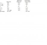
I don't have data that shows that Vbe correlates to anything. I do have models that show what Vce1 < Vce2 means in parallel service: most of the current goes to device one. At .01 ma you don't care if one device does all the work. At 20 amps current, it matters, soa limit as about 2.5 or 3 amps per transistor. If the pros think Vbe cold @ .01 ma predicts 3 amp Vce, fine. I measured roughly 1.2 amp Vce warm. 2 amp Vce measurement would have been better but I didn't have a 3 amp supply at 24 v to use a 10 ohm collector resistor. A 12 V car battery charger would have done a 2 amp test if I had 10 watt 6.8 ohm collector resistor and 68 ohm base resistor.
The rail of 25 thing transistors is fine for getting same production run for industrial parts from the factory via a distributor. One parts pick operation. Less than 25 order will guarentee the parts pick guy will use several odds & ends rails.
NTE is a repackager & I imagine 12 little boxes of transistors from them via a distributor could have come from a dozen different factory runs. There are three or four handling operations in that supply chain to randomize parts source, not one. Unpack at NTE, test repack in individual single part boxes, put on shelf, pull from inventory, ditributor puts on shelf, pulls off shelf, individual boxes of transistors.
Last edited:
And no matter how tempting it is, do not re-use outputs where one or more in a parallel bank have failed. Even if you can get a match to the existing one(s). At least not in a high stress application. The rest will have been stressed to within an inch of their lives, and there may very well be invisible damage - ESPECIALLY with epoxy over molded parts. Do you know why they are only rated for 150C? Because that's where the epoxy melts. If it has locally gone molten and re-hardened it will be a reliability risk.
Hi Guys;
I think I saw the horse move, so here I go again!
I was thinking of values for R1 in thread entry #39 of 1500 ohm for about 10 mA Ib, and 27 ohm for 500 mA Ib. I could go higher, but thought I would play it safe, at first.
The 100k ohm value was a value selected by the original author, as wg_ski indicated, probably selected for small signal transistors(?).
Indianajo;
Is your concern that simply measuring Veb is not sufficient? Could this concern be alleviated by also comparing all devices with your test proposed in entry #31?
Wg_ski;
I completely agree with replacing all 5 outputs in the bank. My only concern is that, in Canada, (and I need to do more research ) , an NTE 2329 is over $10 each plus ax and shipping. Buying 25 pieces is bringing this project out of 'economic viability'.
I can appreciate the concerns of mis-matching in a lot of 12 pieces, so matching to the surviving transistors, with years separating their manufacture, is understandably less likely.
However, and just for the sake of my education; regarding the stress of the survivors, one transistor was found dead shorted E-B-C, Do I have a valid argument here when I suggest that it failed because it's (possible) initial mis-match caused it to hog the current load and send it into thermal run-away? Wouldn't the shorted transistor 'protect' the other devices from any over-current condition? Hope I am not frustrating the experts here, just trying to further my 'knowledge base'.
Trying not to ask questions already covered in a number of "matching" threads, I read in another thread that a shorted transistor was simply removed, and the amplifier then functioned again. Indianajo, you mentioned a Peavey amp that you repaired, had a number of other issues (filter caps, solder joints in feedback circuit path, etc.) Would there be any benefit to temporarily re-installing the 4 remaining survivor outputs, and seeing if the amplifier passes a small signal? (I could power the unit up with my variac)
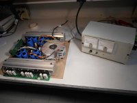
Somebody experienced on sold state told me to match Vce at fixed gain. I did that @ gain 10 1.2 amps Ice. Cheaply. I don't know about the Vbe method, I'm not a production repairman and don't have data on it.
Stressed output transistors that passed double diode test with DVM measured .45 Vcb on DVM 2000 ohms scale instead of .58 that new non-matching OT's measured. They also tended to explode. Follow Wgski advice. Change em all.
Yes, high voltage can get out the base line of a shorted output transistor and blow up lots of stuff back there. You only need 5 OT's to pass 3400 watts, you can run with 4 or 1 for a bit with a high enough resistance load. Use a room heater element in the AC line, a 100W light bulb isn't big enough for this amp to allow test but still limit the energy of the explosions. I blew a TO3 case top to the ceiling my first full energy trial after the 100W bulb box failed to allow anything to work.
If you haven't diode checked the driver transistors already for double diode pass, you're a rosy cheeked optimist.
I'd really try to find some alternative to NTE, personally. Something from ON semi or fairchild div ON semi, preferrably. Or even ST. Set package type, min max collector current , min max Vce, min power requirement, see what distributor has in stock. Then evaluate datasheet. Requires changing more OT's, but you're probably whistling in the dark if you thing NTE parts are going to match anything in ganged AB output service. IMHO.
Last edited:
There's no way on God's green earth that you'll get 5 matching NTE anything. And you will pay way too much for them. Use ON MJL1302/3281. They are not exactly the same as the Toshiba version but they are close enough in the ways that matter for service in a big PA amp. Buy 25 at a time from any of the regular distributors and you've got enough for this amp and the next, and spend about the same as for a handful of NTE's.
MJL21193/4 would almost work. But at that power level they pretty much require TO247 (or even 264) drivers because the beta really only holds up to about 9 amps - and that thing can push more than 45A peak, easy.
MJL21193/4 would almost work. But at that power level they pretty much require TO247 (or even 264) drivers because the beta really only holds up to about 9 amps - and that thing can push more than 45A peak, easy.
Thanks guys;
The ON semi MJL1302A specs look like a great substitute. Is it a concern that the original Toshiba's had a higher Ib? In any case, I am convinced that all 5 outputs have to be replaced, and a 'rail' of 25 will not break the bank.
Indianajo, you mentioned above that this may require changing more outputs, do you mean in addition to the set of 5 in the rail where the shorted device was found?
Attachments
Well, the cheese gets binding;
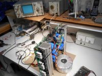
Just for ships and giggles, I re-installed the 4 surviving outputs, leaving the dead shorted transistor out. I attempted powering up the amp. I could not get my variac above 25 volts, because the AC current meter installed on my variac, was full scale at 3.5 amps...and climbing slowly (could this be because of a negative temperature coefficient of the soft start thermisters?) No load was connected to either channel. When the toroid winding cable for the defective channel A, was disconnected, the amp powered up normally, and channel B came out of 'protect'. I 'diode tested' all devices on the heat sinks (including drivers), in circuit, at the start of all this and found only one shorted output. Is this an indication there are other problems, or must all devices be in circuit, in a class H design? The schematic is on page 2, entry #16.
I'm going to re-check all transistors on the heat sinks and check filter caps as per indianajo's entry #8. Apart from the cracked soft start resistors, I can see no other visual signs of damage in the amp. Crude trouble-shooting, but I left the variac at 25 volts, amplifier drawing 3.5 amps for about 30 seconds, I noticed both bridge rectifiers (high rail and low rail) getting very slightly warm, compared to the bridges in the still functioning channel B. I will of course check, but I'm guessing that it is not a cap problem if both high and low power supplies are experiencing a heavy current draw?
I'm getting ahead of myself, but in an attempt to get the front end of this this amp powered up, could I simply remove the driver transistors (Q 110, 111, 124, 125) and leave the outputs installed 'driver-less'? (assuming there are no other shorted outputs)
or should all devices (high and low rail, pos and neg, outputs and drivers, be removed).
I guess what I'm getting at is; where does one look for the cause of this current draw, if if the shorted output has already be removed?
Attachments
For hifi use and wanting a symmetric waveform, if I changed part # on the PNP output transistor, I'd change the NPN's to the matching part # from the same production era. IE buy them at the same time. You want sort of matching gain over the temperature range, and different dies may act very different as they warm up. Enzo warned me about this.
For bass guitar use, in a bar band, unsymmetric waveform probably doesn't matter that much. It just causes even harmonic distortion.
I'm a piano/organ player, so waveforms up to 14000 hz matter to me, and you can hear 1% HD on piano pretty easily. Hard sound to reproduce right, as is glock, another sound I play.
As for troubleshooting the bad channel on your 3400, my Peavey amp had jumpers for the collector lines to the output transistors. I just removed them. I put in fuses but you could put in 1 ohm 25 watt resistors temporarily or something to get a current check to see if your current hog is still the output transistors, or the class H voltage switches. The CS800s has spade lugs from the power chassis to the two channels; maybe you could put a resistor between male & female spade lugs and insert it there.
Pulling the drivers will stop base drive, but would stress the output transistors as an Iceo test.
You could also let the 3.5 amps run longer, and try to see what parts heated up. I've had people tell me to buy a $$$$ thermal imager, but I don't like supporting the oriental economy that much to buy something new.
I did experiment sensing rogue current with a hall effect current sensor, a honeywell SS49 with linear output, but it wasn't sensitive enough.
I've got the current hog problem in my current project, an IC amp, and am going to experiment with compass needles next. I could have wired it wrong but can't feel anything hot, although .85 amp is disappearing with no signal & the light bulb is partially on, dropping Vcc from 30 to 15. I lost my $2 toy compass, and don't really want to subject the $20 lenticular unit for hiking to strong fields, so I'm trying to figure out where to shop to pick up a toy compass without an $8 freight bill. Found the last one in a gas station somewhere.
People also said the mood ring sheets from Edmund Scientific are useful for showing temperature differences. But you have to have a flattish subject to use them. Probably a great device for surface mount parts on a circuit board.
Last edited:
If you've got a high current draw and none of the power devices are found to be bad, check the bias stack (Q105). Make sure the voltage across it makes sense. Try shorting it out and see if the high current goes away. Many times starting there will point you to the fault. Open resistors or diodes can happen and don't discount these either.
Thanks guys;
Indianajo; Yes, 25 Volts at 3.5 amps is almost 90 watts, I would think that something would start smoking real soon, but if there is a dead or near dead short, I guess most of the heat would be in the soft start thermistors (the only parts on the PCB that already look 'cooked'). I would have difficulty with the compass method because this is a double sided PCB and the traces are so close together. What about measuring Voltage across various resistors, comparing chan A to B, but I will have to find that current draw, to allow the line voltage to come up (and allow relay to bypass the thermisters)
Wg_ski;
Do you mean short pins 1 and 3 of Q 105? It appears to be a (darlington). I'm getting in way over my head but;
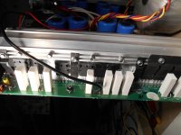
My Crest amp has 7 transistors in each low rail and 6 weird devices (name escapes me). The high and low rails are joined at a common bus. The high and low rails in this Peavey do not seem to have a common connection point between high and low rails. In other words, each low rail transistor seems to have a corresponding high rail 'partner'. Just a thought; I have tried to power up the unit with (dead shorted) Q 117 removed----could it's partner, Q131, left with it's emitter 'dangling', be causing the high current draw?
PS; I'm at hennioriginals@gmail.com if anyone is interested in the manual with schematic and parts list,
Thanks, Peter
Indianajo; Yes, 25 Volts at 3.5 amps is almost 90 watts, I would think that something would start smoking real soon, but if there is a dead or near dead short, I guess most of the heat would be in the soft start thermistors (the only parts on the PCB that already look 'cooked'). I would have difficulty with the compass method because this is a double sided PCB and the traces are so close together. What about measuring Voltage across various resistors, comparing chan A to B, but I will have to find that current draw, to allow the line voltage to come up (and allow relay to bypass the thermisters)
Wg_ski;
Do you mean short pins 1 and 3 of Q 105? It appears to be a (darlington). I'm getting in way over my head but;
My Crest amp has 7 transistors in each low rail and 6 weird devices (name escapes me). The high and low rails are joined at a common bus. The high and low rails in this Peavey do not seem to have a common connection point between high and low rails. In other words, each low rail transistor seems to have a corresponding high rail 'partner'. Just a thought; I have tried to power up the unit with (dead shorted) Q 117 removed----could it's partner, Q131, left with it's emitter 'dangling', be causing the high current draw?
PS; I'm at hennioriginals@gmail.com if anyone is interested in the manual with schematic and parts list,
Thanks, Peter
Enough schematic is posted to be dangerous.
Short the soft start thermistor on the bad side with a soldered jumper, unpower the good side by pulling a spade lug feed (mark wire with tape & sharpie, board spade with sharpie), turn down the variac, and feel around for what is hot. Or use a temperature ray gun.
Standard practice says the short is the other output transistors (since they always change those first in sets without debug @ expensive commercial repair shops) but what do I know. The purpose of the current probe is to answer the question, is the short before or after this point? Not to point to any specific part.
Failing that, pull the other output transistors & do a Iceo test. If it passes 12v test you might need to proceed to 100 v or something, but I found my overstressed ones would hog current c-e at 12 v with the base open. DVM diode test is at 2 v, not enough to break anything down.
Use clip leads and one hand at a time 24 v or over. No jewelry.
Last edited:
Hi Folks,
Sorry for the long delay, I am hoping to revive this thread! (and the amp). Thanks for the great idea; bypassing the soft start resistors and powering up the amp slowly/partially via variac.
I still have a burning question (no pun intended), regarding this experiment:
Can this amp be powered up with one output missing? (Q 117, low rail B- side)
I have checked every other device on the heat sink (in circuit, with Fluke meter) and find all indications identical to the functioning channel. I hesitate to perform this test, I suspect "something's gotta give", and it still may not be the source of the problem...just my uninformed opinion.
Amps like this can be tested (and run) into higher-than-nominal impedance loads with some outputs missing. Just run the same number on both rails. Put in a whole set before you set the bias and put the amp back in service. Most (but not all) amps will drive say 100 ohms or so directly off the drivers with *no* outputs. Another great troubleshooting tool to have at your disposal.
If you've got a high current draw and none of the power devices are found to be bad, check the bias stack (Q105). Make sure the voltage across it makes sense. Try shorting it out and see if the high current goes away. Many times starting there will point you to the fault. Open resistors or diodes can happen and don't discount these either.
Hi wg_ski;
It was just reviewing your previous advice re; bias stack. I must still check those components. I hope 'in circuit' fluke meter checks, comparing chan A to B, will be sufficient. Q 105 appears to me to be a Darlington, IIRC, but again, I hope I can simply compare readings with Q205 (chan B).
I can remove one output from the chan A (problem side), low rail B+ side to balance things. This would be Q 116. My concern, not being familiar with Class H (multi-tier power rails) is; If Q 117 is removed, is Q 131 with it's emitter left 'dangling', causing some current draw issues?
BTW, I have the full schematic and parts list for the GPS 3500 if anyone is interested. Please PM me and I would be happy to forward it. It is to large to attach here. Thanks again, Peter
I FOUND A PULSE!
Thanks to anyone following this slow moving thread. I now have time (and renewed inspiration!) to attack this amp. The latest update; from advice here, I checked diodes associated with the output and found D 133 dead shorted. I don't understand the purpose of this diode, other than protection in the event of some device failure? It is rated at 3 Amp (400 V) and I can not imagine any condition in which it would be conducting.
I replaced this diode with a 3 Amp, 600 V diode and powered up the amp as Indianajo advised; Variac connected directly to the torroid primary, one output; Q117 left out.
Amazingly, the amp came alive! As I increased the variac, the protection relay clicked, there was no heavy line current drawn as I brought it all the way to 110 VAC. I had a signal generator on the input, scope and fluke meter on the output (watching for DC offset). I had no other load on the output. I saw a nice clean sine wave ( maybe 5 volts or so, 1 kHz) and was just about to jump for joy and then....a flash of light, a slight burning smell, and the amp 'flat-lined'!
The flash actually came from a tiny alligator clip, feeding AC to the torroid primary, although I did not see any high current on the amp-meter installed on my variac... I found another shorted output, this time on the POSITIVE side, but also low rail.
Not wanting to end the evening on a 'down note', I removed the blown output Q118 and again powered up the amp. Working again! I thought I would call it a day and consult with the experts!
So my question:
Why did another output transistor blow? and on the opposite rail?
Could it be because I ignored wg_ski's advice about running the same number of outputs on each rail? (in my defense, I did not see any DC offset, before the most recent device failure). Or could failure of devices on Neg rail, have stressed devices on the Pos rail?
In any case, I am looking at replacing all 5 outputs on both rails.
Second question;
Now that the amp seems to have 'balanced itself' (equal number of devices on opposite rails), is there anything I should check before again driving this amp with a larger signal and, as suggested, a 100 Ohm load?
Thanks again, Peter in Canada.
Schematic with missing outputs and replaced diode attached;
Attachments
....found D 133 dead shorted. I don't understand the purpose of this diode, other than protection in the event of some device failure? It is rated at 3 Amp (400 V) and I can not imagine any condition in which it would be conducting.....
Speakers and crossovers can be reactive, inductive. The amplifier current-limit can cut-off abruptly. When that happens is the same as the spark-coil in your car engine. Voltage kicks WAY up. These diodes catch the kick and limit it to just past the supply rail.
I do not know how it could fail except by extended abuse. Good find.
- Status
- This old topic is closed. If you want to reopen this topic, contact a moderator using the "Report Post" button.
- Home
- Live Sound
- Instruments and Amps
- Pet Peeve Peavey (GPS 3500)