Hi Indianajo;
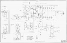
I don't see any B - C caps on drivers for versions A, B, or C. All have 39 pf caps, B - C, on the pre-drivers (last devices on the driver boards). Is this what you are referring to? I wish I knew where I found this, but here is another version of the series A schematic
I don't see any B - C caps on drivers for versions A, B, or C. All have 39 pf caps, B - C, on the pre-drivers (last devices on the driver boards). Is this what you are referring to? I wish I knew where I found this, but here is another version of the series A schematic
Attachments
Yeah, the 39 pf on the predrivers is what I'm talking about as slew rate supressors. If you have one of those, buying special high Ft driver transistors in TO3 may be unnecessary as the driver circuit doesn't have it.
A high freq IM distortion test, or a slew rate test with scope on square waves would tell you if the driver circuit has the high freq capability. I don't have the instruments for that, but I can hear the presence or lack of high freq accuracy with a couple of test records. Peter Nero Young & Warm & Wonderful, when I Fall in Love track has top octave solo Steinway piano. And Martin Denny Hawaii album has a couple of tracks with exotic high freq percussion instruments. The Peavey CS800s can do those, it has no bc capacitors and fast MJ15020/21 driver transistors. One channel of the dynaco ST120 with the original TO5 driver transistors can to the high frequencies; one channel that I replaced with an AX6 board with TIP41c/42c driver transistors can't. I think the 3 mhz Ft drivers on the AX6 board are the speed limit, but both the fast 2SC/2SA transistors I bought to replace them came in F packages with no heat sink. **** ****ese copies from MCM and digikey, were advertised as Toshiba parts with a link to the Toshiba datasheet in digikey's case. Liars.
A cs800 a or b could be as hifi as you want with different driver boards. A lot of the boards discussed on solid state forum have built in TO3p locations along one edge, but you can probably use remote transistors on the Cs800 heat sink with wires over there. I did that on the AX6 board, no oscillation. Don't run the base drive wires and the temp sense wires to predrivers parallel, keep them as far away as possible, was my formula for no oscillation.
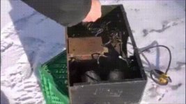
For preventing dirt buildup in future, put a fiber mesh filter in front of the fan. I do that now, the fans on the ST120 heat sink cause a lot of dust on the metal in only a year without. You can cut up a home store filter, or mcmaster sells rolls of the fiilter stuff with adhesive on the mesh for better dust trapping. Tie wraps through the finger guard grill hold the filter on. Looks like ****, but then so does that very used Peavey amp before the washing. We used to steam clean boards that came out of the refrigerator factory that came in looking like that. The repair and re-deploy them.
A high freq IM distortion test, or a slew rate test with scope on square waves would tell you if the driver circuit has the high freq capability. I don't have the instruments for that, but I can hear the presence or lack of high freq accuracy with a couple of test records. Peter Nero Young & Warm & Wonderful, when I Fall in Love track has top octave solo Steinway piano. And Martin Denny Hawaii album has a couple of tracks with exotic high freq percussion instruments. The Peavey CS800s can do those, it has no bc capacitors and fast MJ15020/21 driver transistors. One channel of the dynaco ST120 with the original TO5 driver transistors can to the high frequencies; one channel that I replaced with an AX6 board with TIP41c/42c driver transistors can't. I think the 3 mhz Ft drivers on the AX6 board are the speed limit, but both the fast 2SC/2SA transistors I bought to replace them came in F packages with no heat sink. **** ****ese copies from MCM and digikey, were advertised as Toshiba parts with a link to the Toshiba datasheet in digikey's case. Liars.
A cs800 a or b could be as hifi as you want with different driver boards. A lot of the boards discussed on solid state forum have built in TO3p locations along one edge, but you can probably use remote transistors on the Cs800 heat sink with wires over there. I did that on the AX6 board, no oscillation. Don't run the base drive wires and the temp sense wires to predrivers parallel, keep them as far away as possible, was my formula for no oscillation.
For preventing dirt buildup in future, put a fiber mesh filter in front of the fan. I do that now, the fans on the ST120 heat sink cause a lot of dust on the metal in only a year without. You can cut up a home store filter, or mcmaster sells rolls of the fiilter stuff with adhesive on the mesh for better dust trapping. Tie wraps through the finger guard grill hold the filter on. Looks like ****, but then so does that very used Peavey amp before the washing. We used to steam clean boards that came out of the refrigerator factory that came in looking like that. The repair and re-deploy them.
Last edited:
Turn On Thump!
Hi folks;
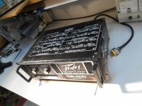
Latest project; trying to pedal a Peavey CS 400 to fund the new outputs for the CS 800. Thanks to all for your help; I learned here to be thorough, and while replacing outputs in the 400, I found an open emitter resistor. All the Vbe matching in the world would not have mattered if I hadn't gone a little further!
Powering up the CS 400 with matched MJ15024's, I found a fairly large turn-on 'pop'. Some web searching leads me to think this could be normal, for an amp with no output relays. My Phase Linear 700B has a worse turn-on thump, after a White Oaks pcb upgrade.
Just wondering if anyone having a history with these amps, could advise on what is considered normal. Is there a simple way to measure this thump? I have a Fluke 75 DVM and a Leader 516 scope, not sure if either of these are capable of measuring this pulse
Hi folks;
Latest project; trying to pedal a Peavey CS 400 to fund the new outputs for the CS 800. Thanks to all for your help; I learned here to be thorough, and while replacing outputs in the 400, I found an open emitter resistor. All the Vbe matching in the world would not have mattered if I hadn't gone a little further!
Powering up the CS 400 with matched MJ15024's, I found a fairly large turn-on 'pop'. Some web searching leads me to think this could be normal, for an amp with no output relays. My Phase Linear 700B has a worse turn-on thump, after a White Oaks pcb upgrade.
Just wondering if anyone having a history with these amps, could advise on what is considered normal. Is there a simple way to measure this thump? I have a Fluke 75 DVM and a Leader 516 scope, not sure if either of these are capable of measuring this pulse
Attachments
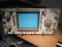
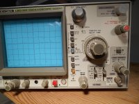
Here is my Scope;
It's old but I'm comfortable with it. (The wife says that about me). I should read the book but hoping for a short-cut here! There is a 'single' button under Sweep mode, if this will capture the turn-on spike, has anyone actually measured these spikes before, and what would be an acceptable limit?
Thanks, Peter, Hillsdale, Canada
Attachments
To see a single shot waveform with a regular scope, you have to be in a dark room. You have to set the scope trigger where it will trip on the transient: and only on the transient. You set sweep to single. fire the circuit under test and as the scope lights up, you close your eyes.
Then you look at the afterimage in your eyes and try to measure it.
Alternately you can build a detect and trap circuit with an op amp a comparitor, and a latch. you use the op amp to flip when the input exceeds a certain voltage. Zeners help.
You use the comparator to see if the op amp flashed over the threshold temporarily. Then the output of the comparitor trips the set input of a flip-flop. (latch). If the led goes on, the latch saw an input and the comparitor saw a voltage higher than the threshhold. If not, not. Reset is either on the latch from a momentary switch, or power off power on reset.
Don't know if the old CS800 thumps; they are not worth much on e-bay. The PV-1.3k and CS800s have thump supression circuits. The PV-1.3k does it without an output relay. It is a jfet on the input that starts out with the output crammed against the supply rail. As the gate goes through a RC timeout, the jfet allows more and more excursion of the input from the supply rail. I looked at the cs800a schematic, I don't see this circuit there.
Last edited:
The old CS and the PL series 2 are very similar - even down to the op amp input stage feeding a PNP level shifter. That level shifter operates between ground and the negative rail - in order for the amp to Center at zero volts, the op amps output must be below ground. If the op amp's natural output offset is positive (would go to + rail with inputs grounded) there WILL be a large thump at turn on. In production, the op amp can go either way, so you've got a 50/50 chance of getting that thump. The BGW level shift circuit, being symmetric, doesn't have near as bad a thump - until the electrolytics in that section age and leakages don't match. I wouldn't build one of these amps without an output relay so it doesn't matter as much. The thump also can prevent these amps from coming up correctly with a light bulb limiter as it stretches the transient out enough for the speaker to draw down the supply. When it does it latches to the rail. Have to leave the speaker unconnected till the bulb goes dim, the all is well for a low power test.
Last edited:
Thanks guys;
I figured out the 'single shot' function on my scope and with repeated trials, my estimation is that the Turn-on spike is at worst; 20 Volts. I had a BGW 410 with turn-CLICK that sounded 'sharper' ( IMHO, more threatening to tweeters). I did not measure it's amplitude, but the problem was resolved by replacing 2 electrolytics in the (VAS) section.
In your opinions, is the 20 V (Peak) thump of the CS 400 inherent in design, or a problem?
BTW;
My next victim will be the Traynor Beta 800...It was poo-pooed here but it is a full complimentary output with a seemingly great fan control circuit. It was also made in Canada, so, in the interest of patriotism, I will try to revive this amp....It is already showing signs of being a new learning experience (more than just blown outputs). I think I have crammed enough amp into this Peeved Peavey thread, so I will start new with "Traynor Training".
Thanks for all the help here, and you all might have a peak at my Traynor dilema,
Peter in Hillsdale, Canada
If your speaker is 300 W music power rated, a 20 v thump is annoying but not damaging.
Per wag-ski, the jfet circuit in the PV-1.3k ensures the op amp input is crammed against the proper rail at turn on, to avoid thump. As he said you can try different op amps on a thumping old CS to see if one randomly goes to the right output. That ancient part number may be hard to find, the pinout looks weird. More secure, you could cram the input of the op amp to a rail at turn on with an auxillary jfet and RC timer, as the PV-1.3k, which see on eserviceinfo.com.
As your thump was caused by tired electrolytics, leave it alone. I change those based on the calender without finding out what sort of damage they can cause.
Best of luck on the traynor.
Hello Peter. I'm new to this forum, I'm from Slovenia and I do not very well in English. I have GPS3400 in a malfunction. PWR LED does not light up. I measured the supply voltage and are OK except for the voltage on the yellow wire of the conector J8 pin 4. What voltage should be between pin 3 and 4? Between pins 1 and 3 and 2 and 3 is 21.5VAC. Thanks.
- Status
- This old topic is closed. If you want to reopen this topic, contact a moderator using the "Report Post" button.
- Home
- Live Sound
- Instruments and Amps
- Pet Peeve Peavey (GPS 3500)