will these work with the 175?AEMC 2152.01 Leads with Test Probes and Alligator Clips for the 1026 & CA7027, Set of 2, Colour Coded, 4ft-
AEMC 2152.01 Leads with Test Probes and Alligator Clips for the 1026 & CA7027, Set of 2, Colour Coded, 4ft
Model: 2152.01 | UPC: 685338159967
Be the first to review this product
Set of 2 color-coded 4 foot (Red/Black) leads, test probes, and alligator clips for the AEMC 1026 Megohmmeter.
REED R1000-KIT Safety Test Leads and Alligator Clips Kit-
Downloads: Datasheet
REED R1000-KIT Safety Test Leads and Alligator Clips Kit
Model: R1000-KIT | UPC: 800837002259
Be the first to review this product
Set of two test leads and two alligator clips.
Sale Price $15.00 USD
Regular Price $17.00 USD
Availability 81 in Stock
Quantity
Search for the "test leads"
Fluke TL26A 5-Way Test Lead Set, 60"-
Fluke TL26A 5-Way Test Lead Set, 60"
Model: TL26A | UPC: 95969083546
Be the first to review this product
Provides five different ways to connect to terminals, this test lead set features 60" (1.5 m), silicone-insulated leads, useable from -112 to 158°F (-80 to 70°C), and is rated for 30 V, 8 A.
Your Price $66.99 USD
Availability 1 in Stock
Quantity
1
Last edited:
ok, I found a used 175 on ebay for just under $200. There are several cheap test leads with clips, here is a link. will these work?
Multimeter Test Leads Kit Banana Plug with Push On Alligator Clips Precision New 783971354258 | eBay
Multimeter Test Leads Kit Banana Plug with Push On Alligator Clips Precision New 783971354258 | eBay
DBT schematic?
testing your transformer is as simple as connecting it to your DBT and measuring the voltage of the disconnected secondary which should be approximately 32 V AC between either yellow lead to the black of the transformer secondary or alternately 64 VAC across the two yellows.
it's good you have clip leads for this test...
sorry for not getting back sooner but Father's Day found me rather busy...
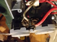
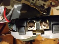
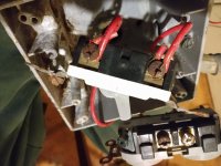
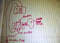
you don't ever have to apologize to me for anything. I have detailed picturesf of the dbt. my art work is that of a 4 year old with a crayon. So, once agaln, White wire comes from AC plug and goes to pic 1 double AC socket with broken jumper contact 1. Red wire goes from contact 2 to the switch, contact 1 in pic 3 then red wire at contact 2 goes back out to AC wall plug. Pic 2 is the other side of dual AC plugs with jumper in tact. Light bulb plugs into either socket.
Attachments
Last edited:
You mean just the transformer? Like blue wire in one side of socket, brown wire in other side?DBT schematic?
testing your transformer is as simple as connecting it to your DBT .
IEC socket? It is mounted in the amp, connected to the UPC socket. The yellow and black wires are not connected. Yes, the IEC SOCKET where the universal power cord goes, it's wired to that. So it's ok to turn the amp on? The power won't go past the transformer as long as it is not connected. And which bulb do I use?
Attachments
Last edited:
Well, after 2 days of trying to figure out why I can't get a steady voltage reading to the DBT, i'm about ready for a rubber room. Let me back track a little. Ok, I could not get a steady reading on any setting and was starting to think the transformer was bad, so I decided to do some damage control and check to make I was getting proper voltage to the DBT. I was using a bad ac outlet, so I found a stable one, but when I plug the DBT in, I don't get more than 10 volt reading that fluctuates down to miliivolts, why? I went as far as to replace the used ac plug sockets and the switch, but nothing was better. The plug and appilance cord that I have wired to the romex tested at 119 volts. That is wire nutted to the 12 gauge #1 house wire that goes to the plug outlet of the DBT. That is where the problem is. How do I fix this?
I just tried hot wiring the DBT and eliminated the switch. Nothing. I got 3 questions.
1. should the light bulb light up if plugged in by itself?
2. Should the fluke show any reading when not connected to any thing?
3. What setting should the meter be on? I have it on auto V which is the 2nd click up from the off position.
4. The signal flow on the DBT should be plug wire in screw 1 on the dual outlet with the broken jumper, then when something is plugged in signal goes to the other side of the outlet, goes across the jumper through the light bulb and exits through the wire out to the plug, right?
- Home
- Live Sound
- Instruments and Amps
- Marshall 3315 missing parts???