Your both right
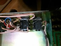
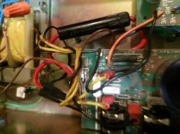
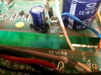
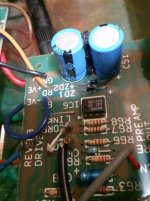
I think it is just adhesive badly applied. There is a visible blob between the 2 that are sitting next to each other. About the fuse holders, can you see the red and black wires that go under the chassis? There are 2 inline fuses there, Could those be replacements for the missing ones on the board? I would gladly take it to a reasonable repair tech if I knew of one. I told the guy at CAE sound about and he was like, "What's it worth to you?" Implying the repair may exceed the value of the amp. I could see paying about $200, but no more. This is where things have gotten out of hand and transformed us to a throw away society. Which is another reason I really want to learn electronics and repair my own stuff. I have complete pictures from one end to the other and the back side as well as the front and rear panel. I'll just keep posting the pics with my replies. Should I get a bridge rectifier?
I think it is just adhesive badly applied. There is a visible blob between the 2 that are sitting next to each other. About the fuse holders, can you see the red and black wires that go under the chassis? There are 2 inline fuses there, Could those be replacements for the missing ones on the board? I would gladly take it to a reasonable repair tech if I knew of one. I told the guy at CAE sound about and he was like, "What's it worth to you?" Implying the repair may exceed the value of the amp. I could see paying about $200, but no more. This is where things have gotten out of hand and transformed us to a throw away society. Which is another reason I really want to learn electronics and repair my own stuff. I have complete pictures from one end to the other and the back side as well as the front and rear panel. I'll just keep posting the pics with my replies. Should I get a bridge rectifier?
Attachments
-
 3315 024.jpg906.2 KB · Views: 98
 -
 3315 025.jpg376.8 KB · Views: 83
 -
 3315 026.jpg421.4 KB · Views: 89
 -
 3315 027.jpg436.6 KB · Views: 85
 -
 3315 028.jpg417.3 KB · Views: 82
 -
 3315 029.jpg377.4 KB · Views: 45
 -
 3315 030.jpg376.4 KB · Views: 37
 -
 3315 032.jpg383.3 KB · Views: 39
 -
 3315 033.jpg343.9 KB · Views: 36
 -
 3315 034.jpg392.9 KB · Views: 41
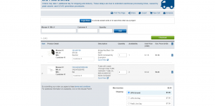
I'm im San Francisco area, just south actually in Pacifica, California, USA 94044. I googled a bridge rectifier for Mbridge rectifier marshall 3315 - Google Shoppingarshall 3315 and a couple of different ones popped up. Does anyone know what the specs might be?
yes, there was no power switch, I put one in, but was not sure which wire went where, so I "hot wired" it. Probably not a good thing, but I figured the power switch on the power strip I had it plugged into would serve the same function, no? At least till I get some concrete instructions on how to wire that. I had a problem soldering the wires to the switch, I think I had no flux at the time, but tried anyway and disfigured the contacts on the switch, do I need a new one again?
yes, there was no power switch, I put one in, but was not sure which wire went where, so I "hot wired" it. Probably not a good thing, but I figured the power switch on the power strip I had it plugged into would serve the same function, no? At least till I get some concrete instructions on how to wire that. I had a problem soldering the wires to the switch, I think I had no flux at the time, but tried anyway and disfigured the contacts on the switch, do I need a new one again?
I have to get somebody to listen for the tone, my hearing drops off sharply at 4k, that was in 1993. God knows it has gotten worse I'm sure. That all started on a 4th of July block party my step father and his friends had **** loads of fireworks and someone lit a 1'4 stick of nitro and it slipped out of his hand right next to me, they ran, I sat there no knowing with my ears uncovered. BLAMMM! RING............................i was 8. Been ringing ever since. Makes it a little chore to do mixing, but I manage. It kills me when something feeds back and everyone goes "Ohwww!' and I go, "What? That's when they did the tone test. Anyway...I'll get back to you. Did you look at those bridge rectifier's on the google link? any of thos the right one?
yes
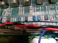
as to the fuses the originals are Pico fuses and are less common as they are pigtailed and require soldering to replace 0275002. - 275 Series - PICO Fuses Axial Radial Thru hole Fuses - Littelfuse
as to the fuses the originals are Pico fuses and are less common as they are pigtailed and require soldering to replace 0275002. - 275 Series - PICO Fuses Axial Radial Thru hole Fuses - Littelfuse
Well, it looks like they left enough metal exposed from the old fuses to solder to, doesn't it? About the bridge, the schematic doesn't really tell me the physical location of if, me being schematic illiterate. Could you give me a hint or 2? Thanks. I got some more pics if you haven't seen where it goes yet. I found another schematic as well. So, this is on the power amp schematic right? Not the preamp section right? or is it all intermingled there? And the link never loads... blank white page. There should be enough in the link description for me to find it though...
Last edited:
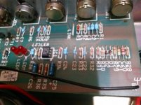
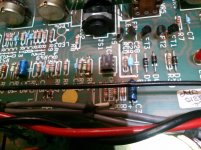
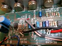
those four pins sticking out of the board,that's where the rectifier goes and don't try and cheat by just attempting to solder to the pins that would be a mistake, if it not apparent yet replacing the bridge and fuses will require you to remove /free up the PCB enough to gain access to the foil side.
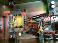
as to the fuses there's three one on the primary side of the transformer which should be a 2 amp fuse ACG type (labeled F3)and then there's the pico fuses on the secondary side those are 10 amp fast blow (labeled F2 and F3)
if you have not done so yet look up and build a DBT (dim bulb tester) and ensure your careful when testing AC portion of a device, what's your utility AC voltage?
if you have not done so yet look up and build a DBT (dim bulb tester) and ensure your careful when testing AC portion of a device, what's your utility AC voltage?
Last edited:
And how do I do this? without mangling it or burning a hole through it. Logical question here before I do anything. What kind of soldering iron should I be using, I have several and soldering sucker attached to an iron and a wide tipped(about the size of a US dime) I imagine for speed melting multiple solder points at the same time. Then I got a Weller pistol grip type and a radio shack version of the same thing. Then I have the basic pencil type, a cordless butane type and the high wattage ( 65, if I'm not mistaken) light blue model and a couple so big you could brand cattle with them.those four pins sticking out of the board,that's where the rectifier goes and don't try and cheat by just attempting to solder to the pins that would be a mistake, if it not apparent yet replacing the bridge and fuses will require you to remove /free up the PCB enough to gain access to the foil side.
Is there any components I will need to check the values of to see if other damage may have occurred. I do have a Tektronics TDS 360 oscilloscope if needed, but you would have to tell me how to set it up. And I got a couple basic volt meters.
- Home
- Live Sound
- Instruments and Amps
- Marshall 3315 missing parts???