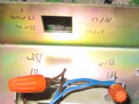
Hi everyone, I'm a green member here (just signed up yesterday) and I've already read some great info. Maybe you all could help me out with a little problem I'm having. I have recently acquired a Marshall model 3315. 150 watt solid state head, which I have no experience with as all my previous Marshall's were tube amp's, mostly JMP late 70's. Anyway I bought this thing for a mere $5.00 at a scrap metal yard off someone that was giving it to them for 1.5 cents a lb. Yep for less than .75 cents. It looks pretty good inside and out except it is missing the red light up power switch, at least I'm assuming that's the type switch. Looks like that one would fit the hole. I bypassed and hooked the wires directly to each other,blue to blue. brown to brown, no power. Fuse is fine. Both inline fuses are good also. Was I wrong to assume the wires went that way? And if you look closely at the hole shot, you may notice 2 conflicting wiring footnotes someone wrote on the inside of the amp chassis and looks like below the transformer it says Bl Brn on the left and bl brn on the right. then near the hole it says blu blu on the left and brn brn on the right, I'm confused. Now inside upon further investigation, it looks like something is missing near where the speaker outputs are and next to a large capacitor (w3437) is there are 4 wires kinda going up from the board to nowhere. See jpeg Picture. There was also a little card on the inside when I opened it up with some wiring memo, can you tell me what it means? Can anyone tell me what is missing, if anything. Thanks for your help in advance...
Brian
Brian
Attachments

Hi and welcome,
The on/off switch is a Double Pole model.
A very common switch.
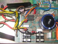
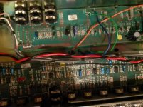
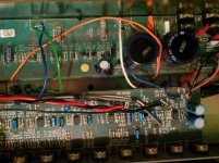
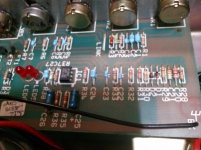
In picture 1, two fuses are missing (F1 and F2, both 10A).
The short pins that are visible are from a removed bridge rectifier.
I suspect a problem with the power amp that took out the bridge rectifier and the fuses.
But that's just a guess.
After replacing these missing parts, do not zwitch on the amp without a Bulb in series with the amp (in the AC line)
If the lamp is on for a brief moment you can take measurements.
But let's see if all is wel with these new parts.
Then come back for more help.
Good luck and be carefull.
The on/off switch is a Double Pole model.
A very common switch.
In picture 1, two fuses are missing (F1 and F2, both 10A).
The short pins that are visible are from a removed bridge rectifier.
I suspect a problem with the power amp that took out the bridge rectifier and the fuses.
But that's just a guess.
After replacing these missing parts, do not zwitch on the amp without a Bulb in series with the amp (in the AC line)
If the lamp is on for a brief moment you can take measurements.
But let's see if all is wel with these new parts.
Then come back for more help.
Good luck and be carefull.
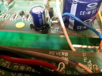
Thanks Tarzan, and no, I don't know how to read a schematic, maybe I can learn on You Tube or Google seems to know just about everything. The 2 fuses you are referring to aren't the in-line fuses(fuse-able links)that are the red wires with the black housings just to the left of the board that is situated one on the top left and one on the bottom left of the picture. Is this thing worth fixing? I do have the schematics for both Power and Pre stages and the reverb.
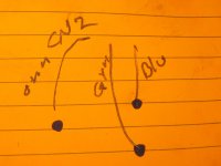
Enzo, The thing is, I can't find anything that relates to the 6 wires in the diagram. Any hint where I might find those?
Enzo, The thing is, I can't find anything that relates to the 6 wires in the diagram. Any hint where I might find those?
So the night is over and I had my first cup of coffee.
Because you can not read a schematic you should consider if it's worth the repair by a technician.
btw, neither of us could in the beginning. I struggled for days to understand the ground markings in a schematic.
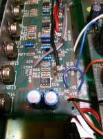
1. Enzo said that the two papers refer to the power transistors (darlingtons).
I see one, but is there a second? Are these still ok?
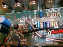
2. Are the potentiometers there?
3. Are the jack sockets for in and output?
4. Then do you see a reverb can in the amp?
That's a box with springs and 2 rca sockets if not wired direct.
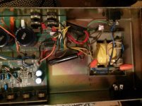
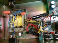
5. Is there a transformer on the chassis?
If all these items are there, then a repair can be done for a fair amount.
The amp itself is a simple one and has a huge power.
You can of course try to do it yourself and looking at your purchase price it can be a nice project.
But only if you follow the recommendations of the forum.
Step by step and in the proposed sequence.
Reply on each and every question with a simple answer.
We do not see the amp and have to rely on your comments.
Now it's up to you.
Because you can not read a schematic you should consider if it's worth the repair by a technician.
btw, neither of us could in the beginning. I struggled for days to understand the ground markings in a schematic.
1. Enzo said that the two papers refer to the power transistors (darlingtons).
I see one, but is there a second? Are these still ok?
2. Are the potentiometers there?
3. Are the jack sockets for in and output?
4. Then do you see a reverb can in the amp?
That's a box with springs and 2 rca sockets if not wired direct.
5. Is there a transformer on the chassis?
If all these items are there, then a repair can be done for a fair amount.
The amp itself is a simple one and has a huge power.
You can of course try to do it yourself and looking at your purchase price it can be a nice project.
But only if you follow the recommendations of the forum.
Step by step and in the proposed sequence.
Reply on each and every question with a simple answer.
We do not see the amp and have to rely on your comments.
Now it's up to you.
Attachments

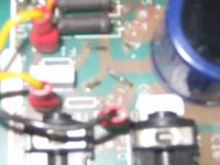
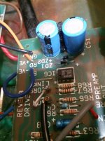
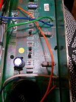
In the first photo is the large capacitor with W3437 printed on it. Immediately above it I see the white, blue, and orange wires soldered to two pins sticking up through the chassis between two screws. If you flip the chassis over, I bet you will see a power transistor. Anchored by the two screws at each end, the pins stick down under the chassis. Similarly, the other three wires probably connect to a similar grouping.
So your output transistors are probably still there, whether they are shorted or not is a separate issue.
So your output transistors are probably still there, whether they are shorted or not is a separate issue.
Hello Enzo,
Nice wording (if this is correct English, I dont know) of the power transistors.
" Anchored by the two screws at each end, the pins stick down under the chassis. Similarly, the other three wires probably connect to a similar grouping."
I have to remember that. So you see, each and every day I'm polishing my English.
It sounds obvious for English speaking people; it isn't always for others.
Thanks
Well, I'm back and the amp is in the same condition it was, I think. It's been in storage and I have moved 3 times, maybe I'll open it up and take some more pictures. I want to take some classes on amp repair, any suggestions? I just acquired a digital scope also. I might need a class just for how it works and how to use it.
Well, I'm back and the amp is in the same condition it was, I think. It's been in storage and I have moved 3 times, maybe I'll open it up and take some more pictures. I want to take some classes on amp repair, any suggestions? I just acquired a digital scope also. I might need a class just for how it works and how to use it.
While he's 99% interested in tube amps, Rob Robinette is worth reading, particularly around safety and how to debug an amp.
The first thing you need is the Marshall 3315 schematic, and then you need to map that schematic on to what you've got sitting in front of you.
Unfortunately, it's a complicated & slightly-hairy* amplifer to start off with, if entirely conventional.
If you're not yet at the point of knowing which end of a 10x probe to hold, perhaps start with some hypersimple stuff, like the Ruby (which RobRob talks about here) or related Run-off Groove projects.
*that is, if mishandled it will let the magic smoke out very quickly. (Once watched a 150W amp's PCB catch fire after simple mistake. Fortunately on someone else's workshop bench, not mine
 )
)

New Pictures !!
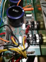
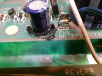
I'm wondering about this black goo on the last picture at the bottom of a capacitor. Is that supposed to be there?
I'm wondering about this black goo on the last picture at the bottom of a capacitor. Is that supposed to be there?
Attachments
-
 3315 015.jpg.jpg422.9 KB · Views: 139
 -
 3315 013.jpg.jpg377.8 KB · Views: 107
 -
 3315 014.jpg.jpg448.6 KB · Views: 134
 -
 3315 018.jpg437 KB · Views: 71
 -
 3315 021.jpg410 KB · Views: 72
 -
 3315 019.jpg447.7 KB · Views: 165
 -
 3315 025.jpg376.8 KB · Views: 62
 -
 3315 030.jpg376.4 KB · Views: 71
 -
 3315 028.jpg417.3 KB · Views: 71
 -
 3315 039.jpg356.1 KB · Views: 96
I'm wondering about this black goo on the last picture at the bottom of a capacitor. Is that supposed to be there?
Good eye! That could be a leaky capacitor. Do you have a soldering iron? If so remove it and either test it (this video will show you how) or simply replace it to be sure.
Some techs and electronic wizards don't mind having someone watching and learning while they work (some do). What, IMO, would be great for you is if you could take your amp to someone who can repair it and explain what they're doing and let you watch and ask questions.
humm i don't think it's leaked electrolyte i think it's silicone to hold the parts, the big caps will have a blob below them but there large enough to conceal the blob.
from these pic's the only thing that appears to be missing is the bridge rectifier and two funky non standard fuse holders.
from these pic's the only thing that appears to be missing is the bridge rectifier and two funky non standard fuse holders.
- Home
- Live Sound
- Instruments and Amps
- Marshall 3315 missing parts???