well soldering to the tabs on this side of the PCB means that the solder on the foil side of the board well get to the melting point and if anything gets physically disturbed you are likely to wind up with a bad solder on the foilside....='s not good...which is why, you need to free up the PC board to get to the underside. if that's too daunting seek help!!
any iron with a good tip and a thirty watt rating is the ticket.
bridge orientation....is diode theory something your not familiar with?
any iron with a good tip and a thirty watt rating is the ticket.
bridge orientation....is diode theory something your not familiar with?
Is there any components I will need to check the values of to see if other damage may have occurred. I do have a Tektronics TDS 360 oscilloscope if needed, but you would have to tell me how to set it up. And I got a couple basic volt meters.
if we can clear the first few hurdles with a DBT we'll possibly get there.
Search results | San Mateo Electronics, Inc.We have one electronics store here, they have pico fuses but I'm not sure if they are the right ones. Can you check this link and see if any of these would work? There are only 12 results.
is this what your talking about?https://www.mouser.com/ProductDetail/Littelfuse/SPXI002T?qs=DPoM0jnrROVDOFOFpVxRtg==
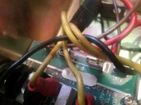
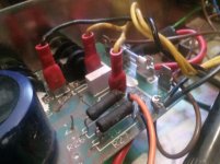
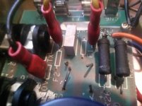
I think you have the fuse numbers mixed up. f1 and f1 are missing f3 is there and good ( it is the glass kind or old automotive type) The power switch has no signal on or off. Here's another angle of the fuses.
Attachments
bridge orientation....is diode theory something your not familiar with?
I'm just not sure which way the signal is flowing and really don't want to put it in backwards. I was always told the only dumb questions are the ones you don't ask. I can free up the board; remove the jack nuts and just get it loose enough to access the underside. I can leave the wires intact, right?
You may find this video helpful for explaining how a bridge rectifier works, which will probably go a long way towards helping you feel comfortable in how to orient it.
Understanding AC And DC, How Diodes Work - YouTube
Understanding AC And DC, How Diodes Work - YouTube
I may have to unsolder something because there is next to no slack at one corner and I will probably damage something trying to flip it. I kinda understand the diode theory in that current only flows in one direction and prevents it from going in the opposite, provided it is aligned correctly. I checked the power switch out again and I did get some signal, not where I expected though. 1st of all it's not a Marshall switch, it's orange and just happen to fit the hole. It's got 6 contacts on the back, not 5 or 4, like most. so, there are 3 on one side and 3 on the other with a divider in between, so left to right there are 3 pairs. I get signal from 1 to 3 and then from 2 to 4 vertical. Is it supposed to go that way? I think I hooked it up 1 to 2 and 3 to 4 a long time ago. Would that have done some damage, like say to the transformer? In it's current state can I test the transformer to see if it works, because if that's the case, I might as well stop now.
And to tell you the truth, I don't think this model had a lighted power switch, I think they were black. It was a blank hole when I got it, so I assumed it had a red light up. I found the orange one and it happened to fit I'm now thinking I should get red one, would a 4 pole contact work for this being there are only 4 wires?
And to tell you the truth, I don't think this model had a lighted power switch, I think they were black. It was a blank hole when I got it, so I assumed it had a red light up. I found the orange one and it happened to fit I'm now thinking I should get red one, would a 4 pole contact work for this being there are only 4 wires?
Last edited:
the silk screen markings and locations are confusing but it is F1 and F2 that are missing
I knew that, you had mentioned F3 as F1 where the glass fuse is as missing, but you see it now right? I made an error on the post and F1 twice when it should have said F1 and F2.
And it is supposed to have a red light up type, the 4 pole will work.
Last edited:

5pcs 5x 10A Littelfuse Pico Fuse 10 Amp 125V FAST BLOW AXIAL | eBayWill these fuses work?
If you're doing anything with mains voltages, it's probably good to acquire a variac, preferably with a current meter. You can tell if your mains transformer works by putting a signal on the primary side, and seeing if it comes out on the secondary side as expected. So if you put 10v AC on the primary, you might see 40v AC On the secondary. That would tell you your transformer is fine.
If you hook up your variac and the current meter starts rising significantly, then you know you have a short.
If you hook up your variac and the current meter starts rising significantly, then you know you have a short.
- Home
- Live Sound
- Instruments and Amps
- Marshall 3315 missing parts???