I was going to build an opamp mixer (for my synths) from scratch, being that the circuits are fairly simple.
But that's a lot of routing, pots, and connectors.
So I had a look at older and cheap mixers on e-bay.
I found that these Kawai (MX-8SR) mixers had plenty of room inside. Plus they were all built with "through-hole" components and single-sided (non-plated through hole), making the part swapping easy.
I was able to buy the schematic online. Not easy to find !! (contact me, I have it scanned)
What I did NOT change, was any switches, pots, and connectors. I also left the "peak meters" alone. The point of this, was to have all the hardware in-place....a real time-saver !!!
I left most of the film resistors alone, except around the balancing output circuit, where I swapped in some precision 10k Vishay's (RNC90y).
Swapped parts (briefly):
All opamps. 4558dd .....to mostly LM4562 (no sockets !).
Disc ceramics....to film types (except for power-supply bypassing).
DC blocking aluminum caps.....to (lower value) film type.
+12.6v PSU.....to new 317/337 @ voltages of my choice, and a new power transformer.
Headphone circuit removed.....replaced with my own (based on Jung composite line driver, AD823/AD815ay)
Notes:
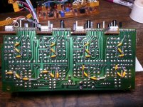
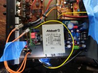
The LM4562 is a "fast" opamp. To prevent stability problems (like oscillation) I added 0.1uf ceramic bypass caps directly to the power-supply pins(4&8) of each opamp, to ground, and another 0.1uf cap directly from pin 4-to-8.......all on the underside of the board. (see pic 2)
There were NO bypass caps there, previously.
I also did NOT use sockets....the new opamps were soldered in place.
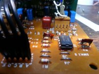
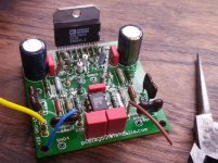
Feedback loop compensation caps used to be ceramic, now they are mica types. Where there were no compensation caps, I "piggy-backed" some 12pf caps, soldered right on top of the feedback resistor (bridging it), just to ensure stability. (I did not calculate this value, I guessed ) (see pic 1)
Preliminary testing....no oscillation ! (I was worried) The new opamps run barely warm to-the-touch.
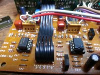
Since there are 8 stereo inputs, I reserved lines 7 & 8 for "opamp swapping", where I did add opamp sockets. This is just for curiosity and testing. Right now, one line has NE5532's, and the other OPA2107's. Will I be able to hear a difference ? Time will tell. (see pic 4)
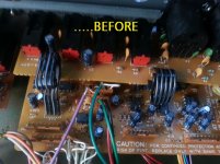
Mixers like this are chock-full of DC blocking caps at the opamp inputs, because a variety of outside signals are fed into the unit which may be passing along unknown DC....making such caps nearly necessary. (see pic 7 "before")
All those caps were previously electrolytics, so those were replaced by film types.
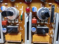
There were a few places that still needed electrolytics.....and I didn't wildly replace ALL of them. The electrolytics left in the circuit were swapped out for newer versions. (I even tried some polymer 'lytics) (see pic 3)
The original headphone circuit seemed weak, as it employed just one 5216p dual opamp, for stereo. I'm adding a separate headphone board I "designed" (actually, Jung did, I copied it for my private use, I made a few adjustments)....that fits quite easily inside. (see pic 5)
The original PSU circuit fed the entire unit with +12.6v.
I am able to raise this to suit the opamps with my new PSU, but I need to think about....if the metering circuits can handle up to +15.5v (??). The output level meter already has trimmer pots for level adjustment.
A (shielded) transformer was replaced accordingly, to suit higher voltages if desired. (see pic 6)
You gotta love the older pc boards.....big holes that when using a wick and a decent iron, de-solder so easily !
Luckily, the schematic was accurate, except for a couple of errors.....and the boards were clearly marked.
But that's a lot of routing, pots, and connectors.
So I had a look at older and cheap mixers on e-bay.
I found that these Kawai (MX-8SR) mixers had plenty of room inside. Plus they were all built with "through-hole" components and single-sided (non-plated through hole), making the part swapping easy.
I was able to buy the schematic online. Not easy to find !! (contact me, I have it scanned)
What I did NOT change, was any switches, pots, and connectors. I also left the "peak meters" alone. The point of this, was to have all the hardware in-place....a real time-saver !!!
I left most of the film resistors alone, except around the balancing output circuit, where I swapped in some precision 10k Vishay's (RNC90y).
Swapped parts (briefly):
All opamps. 4558dd .....to mostly LM4562 (no sockets !).
Disc ceramics....to film types (except for power-supply bypassing).
DC blocking aluminum caps.....to (lower value) film type.
+12.6v PSU.....to new 317/337 @ voltages of my choice, and a new power transformer.
Headphone circuit removed.....replaced with my own (based on Jung composite line driver, AD823/AD815ay)
Notes:
The LM4562 is a "fast" opamp. To prevent stability problems (like oscillation) I added 0.1uf ceramic bypass caps directly to the power-supply pins(4&8) of each opamp, to ground, and another 0.1uf cap directly from pin 4-to-8.......all on the underside of the board. (see pic 2)
There were NO bypass caps there, previously.
I also did NOT use sockets....the new opamps were soldered in place.
Feedback loop compensation caps used to be ceramic, now they are mica types. Where there were no compensation caps, I "piggy-backed" some 12pf caps, soldered right on top of the feedback resistor (bridging it), just to ensure stability. (I did not calculate this value, I guessed
) (see pic 1)Preliminary testing....no oscillation ! (I was worried) The new opamps run barely warm to-the-touch.
Since there are 8 stereo inputs, I reserved lines 7 & 8 for "opamp swapping", where I did add opamp sockets. This is just for curiosity and testing. Right now, one line has NE5532's, and the other OPA2107's. Will I be able to hear a difference ? Time will tell. (see pic 4)
Mixers like this are chock-full of DC blocking caps at the opamp inputs, because a variety of outside signals are fed into the unit which may be passing along unknown DC....making such caps nearly necessary. (see pic 7 "before")
All those caps were previously electrolytics, so those were replaced by film types.
There were a few places that still needed electrolytics.....and I didn't wildly replace ALL of them. The electrolytics left in the circuit were swapped out for newer versions. (I even tried some polymer 'lytics) (see pic 3)
The original headphone circuit seemed weak, as it employed just one 5216p dual opamp, for stereo. I'm adding a separate headphone board I "designed" (actually, Jung did, I copied it for my private use, I made a few adjustments)....that fits quite easily inside. (see pic 5)
The original PSU circuit fed the entire unit with +12.6v.
I am able to raise this to suit the opamps with my new PSU, but I need to think about....if the metering circuits can handle up to +15.5v (??). The output level meter already has trimmer pots for level adjustment.
A (shielded) transformer was replaced accordingly, to suit higher voltages if desired. (see pic 6)
You gotta love the older pc boards.....big holes that when using a wick and a decent iron, de-solder so easily !
Luckily, the schematic was accurate, except for a couple of errors.....and the boards were clearly marked.
Attachments
Last edited:
Sounds very similar to what I did to a Herald RA-88A disco mixer kit. Purchase price $15. Great steel case & slide pots. Hissed badly. I did have oscillation going from JRC4558 to ST33078 "low noise" fast amps. About one megahz. I added a single 0.1 uf ceramic from + to - rail an inch from each pair of IC's, (two rail caps total) and 33 pf ceramic cap across each feedback resistor. There were no feedback bypass caps previously, The 4558 hissed noticeably on the 50x gain RIAA circuits, the 33078 did not. I used phosphor bronze sockets from TE connectivity.
The RA-88A developed a hum problem in the upgrade due to the shielded power transformer (17-0-17) right next to the RIAA stage, so I replaced it with an 18v wall transformer previously from a race car set, 2 1n5344 zeners, 2 resistors, and 2 e-caps in the case to regulate to +-7 v. Herald had killed the hum by putting 330 ohms resistors between power supply filter cap and op amp power pins- cheap but weird. Herald had no filter caps electrolytic or ceramic near the op amps. I did put a PCAT RF filter choke in the case before the filter caps to eliminate CB radio interferance.
I replaced the 10 uf input block caps coming in with 22 uf, but put in new 10000 hour service life grade.
The mixer now sounds almost as good as my dynaco PAS2 tube preamp, but doesn't require switching from one input to the other when I go from LP to CD to FM radio. I used the DJ microphone input potentiometer for the FM radio, a passive input since I use the earphone output of the mono radio. My stereo FM3 tuner doesn't have enough sensitivity for a station I listen to. The disco mixer uses 120 less watts than the dynaco FM2 preamp, so it stays on 18 hours a day.
I bought .0033 uf polystyrene caps to replace the ceramic ones in the RIAA circuit, but haven't installed them yet. It is not annoying enough to proceed so far. I did originally replace carbon film (?) resistors over 100k with metal film, generic 2 watt multicomp (farnell) ones from India. The original build was 1990 so the original resistors were probably carbon film.
Last edited:
Sounds very similar to what I did.......
.....I added a single 0.1 uf ceramic from + to - rail an inch from each pair of IC's,.....
Yes, is what I did. (see my pic #2)
I think modding old cheaper equipment can be a satisfying and a good "learning" experience, for the novice. (me)
In fact, when buying 10-30 year-old audio or test equipment.....if nothing else, I'll automatically replace the PSU smoothing caps to newer versions.
This has often removed hum-and-hiss >>>in a very obvious way.
Well, after 6-8 hrs of circuit tracing, and component checking, I was lead to c58 by loss of signal to #1 side of the mixdown op amp. Sure enough, c58 was not only open, it was physically damaged on the top. This is a great lesson for people like me who instinctively to the under side of the board. If I would have taken a closer look at the top side, it could have saved me hours.
Having the schematic could have saved me hours as well.
Another lesson learned.��
Having the schematic could have saved me hours as well.
Another lesson learned.��
Have been looking for the schematics but can't find them.schematic online. Not easy to find !! (contact me, I have it scanned)
Anyone has them and is willing to share ?
Thank you
Hey! I just grabbed one of these off of Ebay and it has a bad ground hum when plugged in to the first 1/4" socket as well as the first two rca inputs. I have swapped the 1/4" sockets around to see if that was the problem and it's not. Any ideas on where I should start looking next? Thanks for any help
- Home
- Live Sound
- Instruments and Amps
- Modded Kawai mixer