If you find outputs short then check back to the drivers, a simple diode check with a meter will show up if the drivers have fried. If you can find a circuit diagram work back and check over the protection circuits.
This may be better in the Instruments and Amps section where the guitar amp folks are.
Alan
This may be better in the Instruments and Amps section where the guitar amp folks are.
Alan
")
Thanks guys , I'll repost this . I was surprised to see that written on a board . It also says " Make it so ,Number One" . ???
I read somewhere that it is advisable to replace all TIP type units and TR11 .
TR11 is a T2N3904 as listed on the parts list.
TR11 need to be completely covered in Heat Transfer Compound (HTC)
This is to ensure that it keeps the unit biased correctly even when the unit
gets hot. If TR11 is not covered then the fan can cool this component down
and give the board a fault reading of temperature and provide and
inappropriate bias.
No metion of how or what to set the Bias VR or the DC Offset VR tho.
 Moving to Instruments & Amps. Better to send a request to moderation for a move than to create another thread somewhere else. It should get more responses over there..
 Make it so ,Number One
I was going to explain it was a reference to Star Trek, but a quick google of the line tells it all.
Picard - Make It So - YouTube
Build and use a Light Bulb Limiter
Quite probably you still have other bad parts, this will protect your new transistors and let you make some voltage measurements to find them.
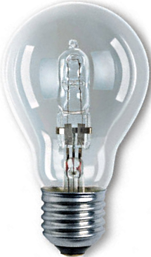
You need a *filament* lamp, not a CFL.
Since 100W ones became unobtainable (unless you have one stashed somewhere) , those "new improved" ones, with a small olive sized quartz halogen filament lamp inside a larger conventional size glass envelope are fine.
Quite probably you still have other bad parts, this will protect your new transistors and let you make some voltage measurements to find them.
You need a *filament* lamp, not a CFL.
Since 100W ones became unobtainable (unless you have one stashed somewhere) , those "new improved" ones, with a small olive sized quartz halogen filament lamp inside a larger conventional size glass envelope are fine.
ahh "the bipolar bear" output on a trace elliot's spent alot of time chasing ghost in these as well as replacing outputs and drivers.
most of the failures with these (depending on the pcb version) that i've repaired all seem to be from high frequency instability usually due to bad grounding (hardware coming loose)and in particular the high frequency bypassing for the output stage which in the early version was connected to a terminal on the corner of the board that also acts as the pcb's fastening point(in some i had to change the hardware. in particular the star point lockwasher)
so if in the process of repairing your amp you remove the board from the heatsink assembly and your Light Bulb Limiter goes bright and the sound fades beware the evil instability(hopefully you have a scope nearby to check it is indeed breaking into oscillation but if your well aquainted with homebrew limiters you already like me know what's happening)
i love the fact that "make it so number one" is on some of the early pcb's it's kinda like finding an old reverb pan by OC Folded Line which are"manufactured by beautiful girls in Milton Wis.under atmosphere controlled conditions" it just goes to show people make these things.
grounding issue
Thanks for the reply . I have read somewhere about the grounding issue . The recommendation was to solder a ring connector to the pad grounding the PCB to the chassis. I have done this and have a wire to the ground lug on the chassis . I will give that a cleanup to ensure it is doing its job.
Thanks for the reply . I have read somewhere about the grounding issue . The recommendation was to solder a ring connector to the pad grounding the PCB to the chassis. I have done this and have a wire to the ground lug on the chassis . I will give that a cleanup to ensure it is doing its job.
The service info recommends replacing the TIP output devices with SC4469 and SA1695 to 'improve' stability. Also TR11 on the underside of the board should be replaced and completely covered - as this biases the output devices, but can be cooled by the fan.....!
I have the schematics and parts lists - if still required?
I have the schematics and parts lists - if still required?
waiting on parts
Thanks . I have all that . TR11 is on the top of the board but under one of the heat sinks.
It is thickly covered by thermal paste so it looks like a little snowman. I think the idea is to insulate it from being cooled by the fan . I dont believe it contacts with the heat sink .
Kinda funny but I havent ever designed an amp .
.
Thanks . I have all that . TR11 is on the top of the board but under one of the heat sinks.
It is thickly covered by thermal paste so it looks like a little snowman. I think the idea is to insulate it from being cooled by the fan . I dont believe it contacts with the heat sink .
Kinda funny but I havent ever designed an amp
.if the light is very bright but fades down that's not all bad but if it's staying lit hard stop double check that the main filter caps and the bridge rectifiers are ok and no offense double check everything transistor polarity's; bypass cap's; solder bridges etc...
if the lamp fades down but stays lit take a reading of the input ac all the while monitoring nothing is heating i'd also check for any dc at the output ( anything more than 0.5 to 0.8 vdc warrants futher investigation)
depending on voltage level the fan and soft start might not operate
if the lamp fades down but stays lit take a reading of the input ac all the while monitoring nothing is heating i'd also check for any dc at the output ( anything more than 0.5 to 0.8 vdc warrants futher investigation)
depending on voltage level the fan and soft start might not operate
Last edited:
no offence taken
Thank you . I was hoping you would reply . I will do just that . I have been trying to test the bridge rectifier by putting 120VAC into it but am only getting 50VDC out . I subed another one for it but no luck . The light is very bright and constant . I will go over everything again and check my work .
Thank you . I was hoping you would reply . I will do just that . I have been trying to test the bridge rectifier by putting 120VAC into it but am only getting 50VDC out . I subed another one for it but no luck . The light is very bright and constant . I will go over everything again and check my work .
well you should disconnect the transformer secondary and power the primary through your lamp limiter if that lights your limit lamp your looking at a transformer short.
i'm not quite sure what your doing by testing diodes with a 120 vac but i hope that was out of circuit!
is there any dc appearing on the output (no load/speaker of course) and what polarity + or -?
and did you before installing you new devices ensure that all remaining components where ok? (i.e.no shorted or leaky caps all remaining small signal transistors verified and no off tolerance resistors)
Eureka . One of my new power transistos were shorted (from the factory ??) . I put the one good old one in and I have sound .
Transformer seemed good as everything worked until I plug in the secondary . I tested the rectifier bridge out of circuit with the 120vac . Unless I was tired , I thought the original onlt delivered 50vdc.
I tested another spare one the same way and got 110vac . I picked out the heaviest spare one I could find and modified it to fit . Prolly not a permanent solution but it is working .
I had done a fair bit of testing in the 3 weeks wait on the parts but since yesterday I did a bit more .
Kinda not sire about the whole Diode Bridge thing as late night troubleshooting tends to be questionable for me !
- Status
- This old topic is closed. If you want to reopen this topic, contact a moderator using the "Report Post" button.
- Home
- Live Sound
- Instruments and Amps
- Trace-Elliot Bipolar Bear