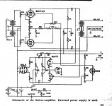
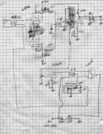
I posted this on GroupDIY as well. I was thumbing through an old ARRL handbook, which had a 6AL5 based side chain for a speech compressor. It looked cool. the input was 'parallel' with the grid of the last triode, before the power stage, and the input to the 'suppressor grid of the first stage' noting that it required a circuit with a pentode input. I'm not a designer by any means, and I googled the heck out of this. Did come across discussions using a 6AL5, and also the "Li'l 4x4" which uses a similar concept, except not with the suppressor grid. I have no idea how to calculate the gain reduction using that method (I generally have no idea how to calculate a lot of things, which is why I lurk here too trying to learn things) but I wanted to take a crack at it anyway to see if anything made sense.
I took the pentode part numbers straight out of the RCA tables for a 6AU6 which seemed close enough to a 6BA6 (what I read suggested you use a remote cutoff pentode) the triode parts from Zugster's triode gain calculator, and the side chain straight out of the ARRL book. (Except I put in larger value pots in place of the fixed resistors for the attack/decay.) I would guess all of that would need some adjustment, and I am wondering if I need all that gain with the pentode as well, I am assuming I could strap the screen grid to the plate, and perhaps no bypass the cathode resistor?
I didn't find anything like this googling, so I am pretty sure I am barking up the wrong tree here, but thought I'd put it up for criticism anyway. Again, I haven't attempted to do any proper math here, and I have no clue how to calc the gain reduction. Also, I am not 100% certain there should be a pot on the input to the triode. The book called for a "single plate to push pull grids" interstage transformer, so I just took a swag at 1:2.
All input including "you don't know what you are doing, go back and study some more" are welcome
Attachments
Last edited:
You'd be better off using the Dogstar option. Making the suppressor grid negative is just asking for trouble, as this will likely lead to instability. The suppressor also has much less influence on the gm than does the control grid. It'll work much better if the control voltage is applied there.
Si diodes also have much lower forward voltages and so don't need their own preamp stage.
As for figuring votage gains, this can be determined by reading off the gm from the "Transfer Characteristics" given in the spec sheet, than determine gain:
Av= gmRL.
Another possibility is to use a pentagrid converter as a voltage gain control amp.
In any case, be prepared to do some empirical adjustments to the basic design.
That output doesn't look right. Either connect the primary of the OPT in series with the plate of the final, or capacitor couple. As it stands now, the primary of the OPT shorted out the 100K plate load resistor.
Last edited:
Some time ago I wanted to do a compressor without the regular methods (vari-mu, opto, etc.) My idea was to attach the anode of a triode dc amplifier to G2 of a small pentode with low G2 current so the triode grid voltage defined the pentodes screen voltage and hence Gm and gain of the stage. The signal chain would be: The pentode with controlled G2 voltage-->triode output stage and in parallel a triode buffer that fed the signal rectifier 6AL5 (just as in the schematic you posted basically)--> to the triode whose anode was connected to the pentodes G2. Best results are achieved with fixed biased on the pentode or LED cathode bias for constant g-k voltage as the screen voltage varies (cathode bias with very big bypass cap might also work but not as well)
I don´t know if I made myself clear, anyhow the circuit worked pretty well for the prototype but I never completely tested it. I think it is a good idea since the screen grid of pentodes is pretty linear as opposed to the intrinsically nonlinear (ie distortion) grid curves of vari-mu devices.
I don´t know if I made myself clear, anyhow the circuit worked pretty well for the prototype but I never completely tested it. I think it is a good idea since the screen grid of pentodes is pretty linear as opposed to the intrinsically nonlinear (ie distortion) grid curves of vari-mu devices.
I'm not sure what you mean by 'part numbers'. Do you mean component values? The 6AU6 and 6BA6 have the same pinout (IIRC) but apart from that are different. The variable-mu characteristic of the 6BA6 only applies to its control grid (g1). The suppressor grid (g3) will be like any other pentode.Blue Jinn said:I took the pentode part numbers straight out of the RCA tables for a 6AU6 which seemed close enough to a 6BA6
Thanks everyone. I've been looking at this a bit further, and also came across a few other compressor circuits using a similar side chain, one with the cv applied to the control grid as suggested here, another applied to the suppressor on a pair of 6BA6's in a strange configuration. I had a computer hardware failue, so a lot of those schemos I need to retrieve from another site, but will post soon. Also, Ian at GDIY noted that single ended is problematic as well, so I've resketched in a push pull input, which will also post. The PRR varimu (which is on the pending build list) has been very helpful in understanding some of the concepts.
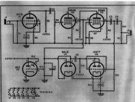
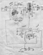
Here is an updated draft, based on some of the suggestions, and the other fragments posted earlier. Scanning and then fixing a mistake with Gimp for some reason was a hassle this time.
I've not done calculations as to the resistor values on the pentodes and I'm not entirely sure about the interstage. This is still a "proof of concept" for me, and a learning tool. I've read other problems (noise) with pentodes, so I'm not sure of the practical application either.
I've not done calculations as to the resistor values on the pentodes and I'm not entirely sure about the interstage. This is still a "proof of concept" for me, and a learning tool. I've read other problems (noise) with pentodes, so I'm not sure of the practical application either.
Attachments

Don't you need a center tap transformer for the input?
Yes, I didn't catch that mistake. Thanks!
The remote cutoff pentodes would normally use DC variation on grid 1 for gain control. 6BA6 however does show grid 2 (not 3) control on its data sheet (last graph), but using large voltage variation:
http://frank.pocnet.net/sheets/093/6/6BA6.pdf
A more suitable type tube are the dual control pentodes, which have considerable grid 3 effect:
6BV11 http://frank.pocnet.net/sheets/123/6/6BV11.pdf
6GY6 http://frank.pocnet.net/sheets/135/6/6GY6.pdf
6HZ6
6AS6
6DB6
6DT6
and then there are ones that have dual - dual control grid 3's:
http://www.diyaudio.com/forums/tubes-valves/160240-suppresor-grid-used-feedback-6.html#post2083661
6LE8 http://frank.pocnet.net/sheets/135/6/6LE8.pdf
6BU8 http://frank.pocnet.net/sheets/093/6/6BU8.pdf
6KF8
6MK8
6GS8
6HS8
and then there are the Beam Deflection Tubes (which can actually do "linear" multiplication):
6AR8
6JH8 http://frank.pocnet.net/sheets/093/6/6JH8.pdf
6ME8 http://frank.pocnet.net/sheets/049/6/6ME8.pdf
Last edited:
The remote cutoff pentodes would normally use DC variation on grid 1 for gain control. 6BA6 however does show grid 2 (not 3) control on its data sheet (last graph), but using large voltage variation:
http://frank.pocnet.net/sheets/093/6/6BA6.pdf
A more suitable type tube are the dual control pentodes, which have considerable grid 3 effect:
6BV11 http://frank.pocnet.net/sheets/123/6/6BV11.pdf
6GY6 http://frank.pocnet.net/sheets/135/6/6GY6.pdf
6HZ6
6AS6
6DB6
6DT6
and then there are ones that have dual - dual control grid 3's:
http://www.diyaudio.com/forums/tubes-valves/160240-suppresor-grid-used-feedback-6.html#post2083661
6LE8 http://frank.pocnet.net/sheets/135/6/6LE8.pdf
6BU8 http://frank.pocnet.net/sheets/093/6/6BU8.pdf
6KF8
6MK8
6GS8
6HS8
and then there are the Beam Deflection Tubes (which can actually do "linear" multiplication):
6AR8
6JH8 http://frank.pocnet.net/sheets/093/6/6JH8.pdf
6ME8 http://frank.pocnet.net/sheets/049/6/6ME8.pdf
Cool. I'm assuming that 6GY6/6BV11 would be better suited than 6BA6?
Something I don't exactly understand is how the thump from introducing the DC control voltage into the signal path is mitigated by a balance control on the cathode resistance. The common control grid on several of the tubes mentioned would obviate the need for an input transformer, but would the opposite phase cv on the suppressor/beam deflectors mitigate the thump? That doesn't seem to be any different than apply it at the control grid.
 Or would fixed bias make a difference?
Attachments
Last edited:
For a balanced P-P type stage, the balanced application of the DC control voltage at turn on would cause a common mode current shift on both sides which would not make it thru the output xfmr. There might still be a small disturbance, even when balanced via the cathode trimmer, due to the gain change, but that should be negligable compared to a DC level shift in one phase.
For single phase designs, you probably have to put up with the thump, since it will mimic a real signal. Maybe it can be applied slowly enough to be subsonic.
The 6BV11 would seem ideal for a balanced P-P type gain control stage using g3 control.
Something like the 6LE8 could theoretically apply the control V to g1 and the differential audio to the two g3's, to get balanced P-P operation, but I suspect the g3 dynamic range is not good enough or linear enough for the audio signal. (try it and find out, it might work OK, worked good enough for TV color anyway)
So (if not) then one would have to use two 6LE8s with diffl. audio on g1 - g1 and control on all the g3's. A single 6LE8 really makes more sense as a manual volume control, with a POT controlling the g3 levels, and single phase audio on g1. The 6LE8 is kind of a low cost BDT. I've seen them on sale for $0.50.
The real BDT are sufficiently linear to put the diffl. audio on the deflectors (g3 equivalents) and the control V on the g1 for current control. But the dynamic range of the deflectors is close to the audio input level and may limit its use at low current (low gain), since the dynamic range collapses as the current is reduced. So you are likely forced to use two of them with diffl. audio on the g1's and control on the deflectors. These BDT tubes are somewhat tricky to use besides, since they are sensitive to external magnetic fields, and may need demagnetizing initially. Typically get Mu metal shields placed around them.
(the 6LE8 should be largely immune to magnetic fields however, since it operates just like a normal dual control grid tube, excess currents get absorbed by g2 rather than deflected)
Last edited:
The 6JH8 and 6ME8 BDTs may not have the problem with dynamic range collapse on the deflectors at low current after all (ie, at low gain set by g1). (if you can believe the datasheet curves anyway)
Earlier attempts to make a preamp with a volume control used the 6AR8 I think, which does appear to have the dynamic range problem on its datasheet curves (see below). Looks like the 6JH8 and 6ME8 also have a full +/- 30 V dynamic range on the deflectors, so these could handle typical audio inputs easily.
http://frank.pocnet.net/sheets/093/6/6AR8.pdf
http://frank.pocnet.net/sheets/093/6/6JH8.pdf
http://frank.pocnet.net/sheets/049/6/6ME8.pdf
Still, these are much more difficult tubes to use. Great if you like to experiment though and have plenty of patience. And for all those 300B SET ultimate linear snobs out there, these BDT tubes actually ARE linear to 1st order (on the deflectors), no stinkin' 3/2's power law here, like triodes. These were the ONLY really linear devices ever......
Hmmm.., got a whole box of them cheap, maybe I should make a highly parallel BDT output stage. Braggin' rights.....
Last edited:
Don't you need a center tap transformer for the input?
No, the CV is going to the suppressor grids not the control grids. Got this mixed up with the PRR at that comment.
Attachments

@SmokingAmp: Do you think this is a viable circuit? It seems simple enough to do on a breadboard, replacing the 6AL5 with rectifier diodes , leaving the attack and decay resistors fixed as in the orig side chain, and tying the screen to plate on a 6BY6 (would prefer to stick with 9 pin) Also, use the auto noise transformers in the same manner as the PRR (No center tap on the input or to the triode, which would require finding an appropriate plate resistor) One thing I'm not sure of is the 1M resistor and pot on the triode (**the one in the signal path not the one in the side chain**) as a means to control the makeup gain. Something tells me there is a problem with doing that after the transformer.
I don't have Spice to try and simulate and I am truly an amateur, but the concept here seems pretty straight forward enough. (Another practical problem for me is how to actually test it--- and to adjust freq response)
The feedback I got at GDIY suggests using the suppressor would work for gain reduction,although I don't understand that either. Again if I am understanding this correctly, putting the cv on the control grid acts like negative feedback to reduce gain? So how does putting a negative voltage on the suppressor grid accomplish the same goal. Or am I am missing something.
Attachments

Last edited:

The suppressor grid reduces gain (or transconductance actually) when it is pushed negative. It causes some of the cathode current stream to be returned to the positive screen grid. The devices are characterised on their datasheet with a constant +V on the screen grid. Connecting the g2 to the plate will cause that gain control to vary in effectiveness with signal level (plate V) I would think. Probably make for some distortion. You could try it and see, I'm guessing it will distort considerably when triode configured.
You need some kind of CT ground reference on the input xfmr to reference the input grids to ground (so they see the bias voltage on the cathode)
No idea how effective the 6BA6 was in the original circuit versus the developed control voltage. I would guess the 6GY6 or other dual control tubes will be more effective, so some downward adjustment of the control V level may be required.
That ground connection on the 1st pot in the control filter looks like it is shorting out the voltage. Ground probably just goes to the bottom wire.
Last edited:
The suppressor grid reduces gain (or transconductance actually) when it is pushed negative. It causes some of the cathode current stream to be returned to the positive screen grid. The devices are characterised on their datasheet with a constant +V on the screen grid. Connecting the g2 to the plate will cause that gain control to vary in effectiveness with signal level (plate V) I would think. Probably make for some distortion. You could try it and see, I'm guessing it will distort considerably
OK. Now I get it. So constant screen voltage. I've been reading about that, a resistor off the b+ bypassed with a large capacitor. The RCA book tables (for resistance couple amplifiers) had fairly large screen resistors.
PRR uses a couple of resistors to 'create' a center tap on the input transformer.You need some kind of CT ground reference on the input xfmr to reference the input grids to ground (so they see the bias voltage on the cathode)
Interesing, there is that one circuit I posted earlier which uses 6BA6 in a strange configuration. PRR called it wacky, and found it to be less useful for thump correction than a push pull. Ebay has a nice prototype board with places for three 9pins.No idea how effective the 6BA6 was in the original circuit versus the developed control voltage. I would guess the 6GY6 or other dual control tubes will be more effective, so some downward adjustment of the control V level may be required.
I misdrew the filter, the connection is in the wrong place, I'll double check the ARRL book but I am pretty sure the original (single sided draft I posted first) has it correct.
Attachments
Last edited:
You might want a small cap from screen grid to cathode on the 6GY6 or whatever to hold the Vg2 constant. The high value screen grid resistor is commonly used to drop the voltage from B+, but it doesn't hold Vg2 constant against current change unless the signal is really small.
- Status
- This old topic is closed. If you want to reopen this topic, contact a moderator using the "Report Post" button.
- Home
- Live Sound
- Instruments and Amps
- Pentode pre/compressor (warning nube attempt at circuit drafting) --suppressor grid