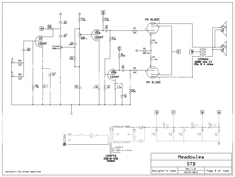
This circuit is basically copied from something I found on the net (ballsy simple design), but I'm subbing in 1960's Fender transformers. I just wanted to run this drawing by the forum and see if you notice any deficiencies in the circuit before I start putting it together.
Also, 50V should be a high enough rating for C6 and C13, right?
help and/or comments appreciated
Also, 50V should be a high enough rating for C6 and C13, right?
help and/or comments appreciated
Hmmm... yerrrrrr...
I'll be even more direct and ask what you are trying to acheive
I'm all for innovation and such but fail to understand what this is about....
What kind of sound are you trying to acheive with this design and what are you planning to plug into it??? Please don't misunderstand my questions... I just cannot imagine how it'd work with an electric guitar (the instrument traditionally associated with a need for a 'ballsy' sound - unless this is for a Hammond or other electronic keyboard???)
Any road... I'm usually pretty good at spotting where this sort of stuff originates but you've got me stumped... I'm not a great fan of inputs that go through a cap at the start of the audio chain at any rate...
perhaps you can build it and prove us wrong
Nor have I ever seen a full wave bridge used with a CTed HT winding... unless I am mistaken it should be a half wave rectifier if the CT is grounded... otherwise you'd wind up with a voltage in excess of the capability of your valves and any single filter caps that I know of...
Another convention that is odd is that the filter stages are lettered backward to how most people would have... ie usually the first filter stage would be denoted as 'A', second 'B' and so on... doesn't make it wrong... there are no rules as such... it's just odd...
These are just a couple of things that make the schematic smell a bit of inexperience... and well... possible danger to anyone who might follow it without questioning it's validity...
Last edited:
This schematic has never been built as is. Consider it to be the first draft by someone who has never designed or build a tube amp, or a guitar amp. Sorry if that's the OP.
1) Voltage gain is low and half a 12AX7 is unused.
2) Power supply problems as Enzo mentioned above.
3) Power supply will likely go over 500V at idle so caps need to be rated at 550V or higher, or series stacks need to be used. The voltage is actually too high for a cathode biased 6L6 output stage. A 300-0-300 transformer would be better.
4) Power tubes need screen resistors.
5) Although the 6L6GC data sheet specifies 0.5 meg for grid resistor in cathode bias, a lower value would be prudent.
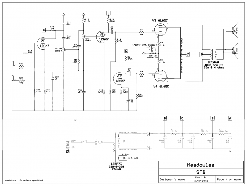
6) Power tubes' bias will likely be too hot with 200 ohm cathode resistor. That resistor needs to be 10W rated, 250 to 330 ohm. A bypass capacitor of perhaps 100uF at 100V would increase gain and give more tube like distortion.
1) Voltage gain is low and half a 12AX7 is unused.
2) Power supply problems as Enzo mentioned above.
3) Power supply will likely go over 500V at idle so caps need to be rated at 550V or higher, or series stacks need to be used. The voltage is actually too high for a cathode biased 6L6 output stage. A 300-0-300 transformer would be better.
4) Power tubes need screen resistors.
5) Although the 6L6GC data sheet specifies 0.5 meg for grid resistor in cathode bias, a lower value would be prudent.
6) Power tubes' bias will likely be too hot with 200 ohm cathode resistor. That resistor needs to be 10W rated, 250 to 330 ohm. A bypass capacitor of perhaps 100uF at 100V would increase gain and give more tube like distortion.
An on-going saga... Just build the darn thing and see if it works already... if not, figure out why.
Just build the darn thing and see if it works already... if not, figure out why.An on-going saga...
Hmmm... I like to know that it's going to be close to working and at least safe when it does... you can call me an old fart... but I like to build something that works and then freak around with it...
This is a mish-mash of
 bits and pieces that is likely to be more trouble than it's worth...
Good luck... you're going to need it
OK - so I'm a thick-o... - who hasn't a clue what you mean by 'OP'...
I was merely expressing my opinion - which is what forums are for - that some of the basics (like the rectifier) were completely wrong for a start... and that the more I look at it - the more I think it's going to take a lot of backward engineering to make it stable - which - in my experience will more than likely nullify the whatever innovation the author is trying to acheive... it's a funny thing... but nobody's really come up with anything new... apart from unstable designs... where the use of standard output valves are concerned... and there is a sound and fundamental reason for that.
But OTOH - I did say build it and prove me wrong in post #3...
So knock your socks off... it's no odds to me... I am just stating an opinion with no desire to get into a flaming match... good luck...
- who hasn't a clue what you mean by 'OP'... I was merely expressing my opinion - which is what forums are for - that some of the basics (like the rectifier) were completely wrong for a start... and that the more I look at it - the more I think it's going to take a lot of backward engineering to make it stable - which - in my experience will more than likely nullify the whatever innovation the author is trying to acheive... it's a funny thing... but nobody's really come up with anything new... apart from unstable designs... where the use of standard output valves are concerned... and there is a sound and fundamental reason for that.
But OTOH - I did say build it and prove me wrong in post #3...
So knock your socks off
... it's no odds to me... I am just stating an opinion with no desire to get into a flaming match... good luck... An on-going saga...
That thread you linked to was a completely different idea/effort [which has since been scrapped] than this one.
The OP is not interested in copying working circuits, that would too easy, so trial and error it is...
This schematic that I posted in THIS thread is pretty much a straight copy of an old Supro amp, so your hopes and dreams of me copying working circuits has come true!
Look, I may ask some questions that are either tedious, boring, short sighted or just plain don't make sense to some of you. That's because I am very much a novice builder. There are many parts of these circuits that I just don't fully understand... YET. I'm working my way through it, and in time I promise to make my questions more interesting for some of you more seasoned hobbyists/techs. But in the meantime, try being either constructive or absent
And thanks to you guys that have offered some help. I will change the rectifier and look at the other concerns.
Here's a link to the schematic I copied. What drew me to it was that it is the most simple dual output tube schematic I've seen, plus I like the sound of old Supro's. And furthermore, I have a pair of transformers from an old 60's Bandmaster and a nice pair of old GE 6L6's to go into it. That makes this project very affordable for me because all I need is some general inexpensive parts to implement it.
http://usdn3.nodevice.com/preview/big/373/373418-2.jpg
You can use a full four-diode bridge and leave the center tap not connected, or you can use two diodes and ground the center tap. In the first place you will be rectifying the entire winding voltage into DC. If you ground the center tap, you are then rectifying half the voltage of the winding, so the result will be much different.
Here's a pdf of the same schematic I copied with some additional information. There's a note about the cathode resistor value on there too. http://www.angelfire.com/mech/beansamps/schems/S6420.pdf
The only things I changed were the PT CT, I moved the bulb to be fed by 6.3vac instead of mains voltage, I added 1 ohm sense resistors on the cathodes of the output tubes, and I also plan on adding a standby.
The only things I changed were the PT CT, I moved the bulb to be fed by 6.3vac instead of mains voltage, I added 1 ohm sense resistors on the cathodes of the output tubes, and I also plan on adding a standby.
If you still want to only use 3 triodes, just use a 12av6 as the first tube, and maybe you can use the signal diodes as clipping diodes such as in a distortion pedal. Otherwise, using the remaining 12ax7 half as an additional gain stage would make it much more usable for passive guitars or even bass.
- Status
- This old topic is closed. If you want to reopen this topic, contact a moderator using the "Report Post" button.
- Home
- Live Sound
- Instruments and Amps
- seriously thinking about building this schematic. Can you find any issues with it?