...magnetic flux density in the core is roughly proportional to current and total number of turns...
From electromagnetic theory, magnetic flux at the centre of a long solenoid is (mu * n * I), where n is the turns per unit length, and I the current.
Turns per unit length equals total turns divided by length, so in a specific transformer, total number of turns in a winding is proportional to turns-per-length for that winding. Substituting this in the formula above, we conclude that the magnetic flux density in the core is proportional to the total number of turns in the winding, multiplied by the current through the winding, multiplied by the "mu" of the magnetic material.
Voltage should enter indirectly, in the sense that it (along with coil impedance) drives the current in the coil.
There are also quite a few of these amps using 100V audio line transformers, in countries where that is the standard. The Aussie Guitar Gearheads forum is full of them, usually running on B+ more than 300 volts DC.
I did think of the 50C5 and family, mainly because of the low 2700 ohm primary Z. Using only half the 6.3V winding on the speaker side may make some other valves usable, since the primary impedance is now up in the region of 11 kilo ohms. I think a single-ended 6AK6, for instance, is reasonably happy with a 10k OT.
And yes, guitar only. I have less than zero interest in valves for Hi-Fi. In my world, Hi-Fi is supposed to be accurate, and transistors do that far better than valves do. But e-guitar needs euphonic distortion, lots of it, and valves are very good at distorting for the same reason they are bad at being accurate.
-Gnobuddy

I only mentioned it here because I was surprised at how wide the transformer's bandwidth was. Especially considering that it was designed only to power 6.3 volt valve heaters with 60 Hz AC.
But we all like the idea of a random little power transformer unexpectedly turning into a surprise guitar amp output transformer, so I may take this a little further.
-Gnobuddy
??No. Voltage.
From electromagnetic theory, magnetic flux at the centre of a long solenoid is (mu * n * I), where n is the turns per unit length, and I the current.
Turns per unit length equals total turns divided by length, so in a specific transformer, total number of turns in a winding is proportional to turns-per-length for that winding. Substituting this in the formula above, we conclude that the magnetic flux density in the core is proportional to the total number of turns in the winding, multiplied by the current through the winding, multiplied by the "mu" of the magnetic material.
Voltage should enter indirectly, in the sense that it (along with coil impedance) drives the current in the coil.
Then how do we explain large numbers of DIY valve guitar amps using 70.7 V audio line transformers, and running on B+ of a few hundred volts?At 115V a commodity power transformer will be high THD. You want to aim audio under 1/3rd rated voltage. So 40Vrms, 56V peak, which suggests a B+ far under 100V.
There are also quite a few of these amps using 100V audio line transformers, in countries where that is the standard. The Aussie Guitar Gearheads forum is full of them, usually running on B+ more than 300 volts DC.
This should be dictated by primary inductance and reflected load impedance, no? Transformer impedance drops by 3 dB at the point where the primary's inductive reactance equals the reflected load impedance at the primary. Current goes up 3 dB at this point, and then rises at 6 dB/octave below that, which we know will make the core saturate (and mu fall) at some low-enough frequency.Of course depending on your lowest note and tolerance for distortion.
It may be a fine thing for a 50C5 at 110VDC on *guitar*. Not working to 60Hz, not expecting "clean".
I did think of the 50C5 and family, mainly because of the low 2700 ohm primary Z. Using only half the 6.3V winding on the speaker side may make some other valves usable, since the primary impedance is now up in the region of 11 kilo ohms. I think a single-ended 6AK6, for instance, is reasonably happy with a 10k OT.
And yes, guitar only. I have less than zero interest in valves for Hi-Fi. In my world, Hi-Fi is supposed to be accurate, and transistors do that far better than valves do. But e-guitar needs euphonic distortion, lots of it, and valves are very good at distorting for the same reason they are bad at being accurate.
-Gnobuddy
The only thing special about this transformer is that it happened to be within reach when I searched around for something to test the Syscomp Circuitgear Mini on.Such transformers are just as common with 230V primaries, allowing B+ in the 200 to 250 volt range depending on how low in freq you need it to go.
I only mentioned it here because I was surprised at how wide the transformer's bandwidth was. Especially considering that it was designed only to power 6.3 volt valve heaters with 60 Hz AC.
But we all like the idea of a random little power transformer unexpectedly turning into a surprise guitar amp output transformer, so I may take this a little further.
-Gnobuddy
Much of my youth was spent making guitar amps out of stuff I rescued from the local trash dump. The OPT in a push pull amp was usually the power transformer from a small radio, TV or HiFi set. Use the center tapped HV winding for the primary, and all the heater windings in series for the speaker. The original primary was not connected. More often than not, they worked just fine for guitar amps....note, at that age I did not understand things like impedance, but do remember that the amp got louder and louder as more speakers were connected to it.
For small SE amps I used the vertical sweep output transformer from a TV set. The vertical sweep section is a purpose built class A SE audio amp designed for one frequency, 60 Hz in the USA. Often the entire vertical section could be lifted from the TV verbatim, just break the feedback and sync connections and insert a guitar jack. Want tone controls or distortion, add a preamp. 12AX7's weren't too common in the trash, but 6AV6's and 6SQ7's were. They were essentially half a 12AX7.
In both of these cases the transformers were intended for 60 Hz operation but had treble response exceeding the capabilities of any speaker I could find for zero money back then.
Another simple way to test a transformer for shorts. Use a cheap amp that can survive a shorted output. I have a small chip amp that makes a few watts. Drive it with an oscillator, a sound card, or even a musical instrument that can produce a reasonably clean waveform that resembles a sine wave.
An old tube type HP audio oscillator works excellent for this. I used a model 200AB, it will put about half a watt into an 8 ohm speaker, no amp is needed.
Connect it to the speaker output, or heater winding, apply a few volts of audio from the amp into the transformer. Even a cheap DVM can be used to measure this, since absolute accuracy is not important. Measure the voltage on the other windings to see if the ratios are roughly what you expect. A winding with a short will cause the transforner to draw excessive current and produce little output. If the short is on the primary side of a P-P OPT, the halves will be severely unbalanced.
CAUTION, as with the battery method, you can receive a nasty shock doing this, so use clip leads and don't touch any wires......
It is possible to make up a little test fixture for exploring junk transformers using the same method. Use an audio source that's reasonably clean, put a 6 or 12 volt light bulb (i used pilot light bulb) in series with the amp (it will glow with a shorted transformer and protect the amp. Put resistor loads on all the other windings, something in the range of 10K just to damp out ringing. Use some sort of meter that is reasonably accurate well into the audio range. I used an old HP331A distortion analyzer. This way you can accurately measure the ratio and get an estimate of the transformers frequency range.
As myself and others have stated a transformer will behave differently depending on the circuit it is used in. This is especially true when something is being repurposed as an OPT. Enclosing a "mystery transformer" inside a feedback loop can have unpredictable results. Sometimes it works good, sometimes it makes an amp into a very loud oscillator.
That's quite interesting. I've read several threads in which someone gets shot down for suggesting the use of a power transformer as an OT, because everyone "knows" it will have a terribly inadequate frequency response.In both of these cases the transformers were intended for 60 Hz operation but had treble response exceeding the capabilities of any speaker I could find for zero money...
Apparently that falls into the category of "Things we know that are not so."
Thanks for that suggestion. NE-2 neon bulbs seem to be on the edge of extinction, so it's nice to have an alternative.Another simple way to test a transformer for shorts. Use a cheap amp that can survive a shorted output.
The Barkhausen stability criterion is unforgiving!Enclosing a "mystery transformer" inside a feedback loop can have unpredictable results.
Yesterday was busy, as predicted, and I didn't have any free time to tinker with the little transformer. We'll see how today goes.
-Gnobuddy
NE-2 neon bulbs seem to be on the edge of extinction
Over 4,000 in stock at Mouser, and still being made. I use them for H-K protection on cold start in some of my designs. Some people use a diode, but I'd rather have a fixed 1pF cap (the NE-2) than a Voltage Variable Cap (the diode) wired into my audio path.
C2A VCC | Mouser
Enclosing a "mystery transformer" inside a feedback loop can have unpredictable results.
I have found unpredictable and totally weird issues when doing so. Even wiring a differential feedback path in a push pull amp by grounding the 4 ohm tap and taking feedback from the 0 and 16 taps can lower the distortion ad mid frequencies, yet totally whack the frequency extremes due to winding imbalances. This happens with my large stash of guitar amp OPT's, yet some 60 Hz power toroids with two equal heater windings respond well.
Some power transformers work good, some suck, most work good enough for guitar. I did try to use a microwave oven transformer for an SE OPT once. That was the definition of SUCK, high end rolled off at about 400 Hz.
Nope! I have zero emotional investment in this transformer, and I'm not sure what you mean by "magnetic shunts".Did you at least take the magnetic shunts out first?
If the transformer works as an OT as-is, fine. If not, it will sit in the junk-box until I need 6.3V AC heater power for some project.
It did rather better than that, completely unmodified.Maybe get you to a couple kHz.
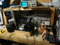
I decided to make a quick manual sweep with the old function generator and 'scope before I futz around with installing drivers and software for the CircuitGear Mini on my ancient laptop.
I drove the transformer primary with an AF function generator (50 ohm Rout) with a 2.2k 5% resistor in series. The secondary (6.3V winding) was loaded with an 8.2 ohm 1% resistor.
I set the AF gen for 5 mV pp across the 8.2 ohm resistor at 1 kHz, then manually went higher and lower in frequency in search of the (roughly) -3 dB points. They were at around 20 Hz, and at around 10 kHz.
So not quite the very impressive 100kHz that showed up on the unloaded measurement, but 10kHz is still more than adequate for electric guitar.
I may have more data for you later, depending on how cooperative my old laptop turns out to be.
Edit: I just realized I had my cheapo 100x 'scope probe already installed, which is why the signal level was so low. Assume +/- 50% error in those rough measurements above, then, due to the signal being nearly in the noise floor.
-Gnobuddy
Last edited:
I was referring to George’s MOT experiment. Those things usually have two little pieces of trafo iron partially shorting the flux around the primary to intentionally reduce the coupling. Regular power transformers don’t have this because it causes it to drop voltage like a stone under load. Normally not what you want, but in microwave ovens, battery chargers, or Tesla coils it is exactly what you want as it will tolerate a shorted secondary. Since it acts like a big series L, the higher the frequency, the more drop. I have successfully knocked the shunts out before (they are usually press fit) to use MOT’s as a more normal HV transformer. Still runs at a really high flux density, but better regulation. With the shunts in place, at audio frequencies, it would suck about as much as a Dyson.
I was referring to George’s MOT experiment.......two little pieces of trafo iron partially shorting the flux around the primary
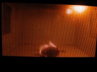
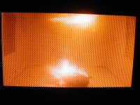
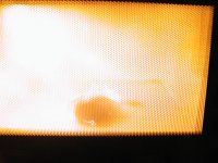
I had collected several MOT's for science experiments. Most were from ovens that I found in the trash, or that I blew up doing .....science experiments, like making a plasma ball big enough to melt the glass floor in the oven.
At the time I knew that the MOT operated in a semi resonant, edge of saturation mode, but didn't know about the shunts. The magnetron is a vacuum tube that self oscillates due to a resonant cavity inside and a BIG magnet on the outside. It produces 500 to 1000 watts of RF power at 2.45 GHz which excites the water molecules in the food. If there is no food in the oven this RF power has nowhere to go except to be reflected back into the magnetron tube. This raises its plate dissipation from 300 to 500 watts, to roughly 1500 watts, which will quickly cause it to self destruct. The early Amana Radar range and Litton commercial ovens did exactly that!
To combat the meltdown and make the oven lighter and cheaper, a rather unique power supply was designed. It uses a transformer, a capacitor and one diode to make a half wave voltage doubler. The magnetron tube itself is the second diode, and there is no second cap. This setup is not only a voltage doubler, it is a series resonant circuit at roughly 60Hz. When the oven has a full load of food the tube draws a certain amount of current, and its plate resistance is high enough for the resonant circuit "Q" to allow the tube voltage to rise into the 2500 to 3000 volt range and the oven operated at maximum power. With nothing inside, the tube becomes a low impedance dropping the circuit "Q" and the tube's plate voltage. The oven will draw less than 1/3 it's rated power, preventing tube meltdown or serious arcing from RF standing waves. The magnetic shunts in the transformer core also play a part in the transformer / power supply's self limiting action.
When my 41 year engineering career ended I had to move all my belongings 1200 miles. I knew this was coming several years in advance and started downsizing my stuff, by selling, giving away, or trashing it. Even with about 5 years of this over 1000 pounds of transformers went to the metal scrapper in the last few months. I couldn't even give the big stuff away for free at hamfests. I had THREE 1500 volt 1/2 amp constant voltage power supplies from Motorola base station transmitters. They went to the scrapper. One can be seen here making an 833A glow pretty. The big panel on the left standing on its end. Yeah, that SOLA transformer weighs in at about 70 pounds.
I included a few pictures of a "science experiment" that killed an oven. It was still working, but the cavity was breached.
Attachments

Thanks for the explanation! I knew about constant voltage transformers, but this is the first I've heard about what is essentially a constant current transformer...or at least, a step in that direction....Those things usually have two little pieces of trafo iron partially shorting the flux around the primary to intentionally reduce the coupling.
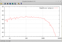
In other news, I finally persuaded the Syscomp CircuitGear Mini to do its thing with the little Hammond filament transformer. Result: no good as an OT, unless you're happy with a 2 kHz upper cut off frequency! (But shockingly, it goes down well below 10 Hz - maybe below 5 Hz - with very little drop in voltage.)
This was still fed from 2.2k source impedance, and with the output loaded down with 8.2 ohms.
I experimented with driving the primary directly from the CircuitGear Mini (150 ohms source impedance) as well. There was negligible change to the high frequency response, but the bass response was extended down to a ridiculous 1 Hz or so.
I'm happy; the only reason I grabbed the transformer in the first place was to get the CGM working and learn how to use it to measure frequency responses, and it would seem I've done that.
Measured frequency response attached. The y-axis is in dB, the x-axis in Hz. The signal level is low because this is a transformer with quite a high step-down ratio, and the audio function generator in the CGM outputs a maximum of only +/- 2.5 volts peak.
-Gnobuddy
Attachments
Old style fluorescent tube chokes have iron cut in weird shapes, which do as described above: turn them into lossy inductors which to boot tolerate better the shorted load which is a fluo tube.
Or simply the center E leg is slightly shorter, 1 or 2 mm, so like it or not you have a significant gap there.
Or simply the center E leg is slightly shorter, 1 or 2 mm, so like it or not you have a significant gap there.
Gnobuddy, that's likely a good result for a guitar application where roll-off from 5kHz if sort of acceptable. Also worth noting the generic rising impedance of any guitar speaker with frequency, which could well counter-balance the OPT droop with fixed resistance loading.
Many guitar amp DIY'ers are quite happy with their recycled or re-purposed mains transformers as output transformers - as you have noticed over on aggh forum - so it's good to see an example frequency response plot. The advent of soundcard and software to use as an alternative to what was an array of bench equipment makes it fairly easy to do this type of testing even with a simple battery powered amp module as the signal generator source.
Many guitar amp DIY'ers are quite happy with their recycled or re-purposed mains transformers as output transformers - as you have noticed over on aggh forum - so it's good to see an example frequency response plot. The advent of soundcard and software to use as an alternative to what was an array of bench equipment makes it fairly easy to do this type of testing even with a simple battery powered amp module as the signal generator source.
In other news, I finally persuaded the Syscomp CircuitGear Mini to do its thing with the little Hammond filament transformer. Result: no good as an OT, unless you're happy with a 2 kHz upper cut off frequency! (But shockingly, it goes down well below 10 Hz - maybe below 5 Hz - with very little drop in voltage.)
-Gnobuddy
The real limitation on the low end is how much voltage you can throw at it at a given frequency. At 50 Hz, you should be able to develop maybe 150V on the primary side before things go south. At lower frequency it is less. Where it goes nonlinear is a totally separate issue from where it rolls off due to (small signal) magnetizing inductance. Too bad inexpensive filament or control transformers aren’t generally available with 480 volt (dual 240) primaries. That would be a game changer for cheapskate guitar amp builders
?? From electromagnetic theory, magnetic flux....
The current in a coil is opposed by inductance. You can think of a "back EMF" due to inductance. For AC drive the current goes by voltage, inductance, and frequency.
I won't argue the wide use of 70V transformers in guitar applications because this is more art than technology.
Later today I did a second frequency response measurement, this time with the 8.2 ohm resistive load wired between the centre-tap and one end of the 6.3V winding. The treble droop moved significantly higher in frequency, the response now being -3 dB at about 8 kHz instead of about 2.5 kHz. IMO that is definitely usable for e-guitar....that's likely a good result for a guitar application where roll-off from 5kHz if sort of acceptable.
(Questions about the transformers ability to tolerate DC bias current for SE use remain unanswered, however.)
Perhaps you remember, I asked you in another thread about the hardware interface you were using between sound-card and device under test.The advent of soundcard and software to use...
The need to build such an interface is one of the reasons why I haven't adopted sound-card measurements sooner; that, and the fact that I use Linux, and didn't particularly want to be dragged back into the world of Microsoft after eighteen years.
Then I stumbled across the Syscomp CircuitGear Mini. It's almost perfect for my purposes: it's a 2-channel USB 'scope with 11-bit vertical resolution (much better than any of the affordable digital scopes). It includes an arbitrary function generator, and does automated frequency response measurements. It comes with BNC input and output jacks, and accepts generic oscilloscope probes - I don't need to build a hardware interface for it. It's got more than enough bandwidth for audio measurements. And all this at about one-tenth the price of most of the usable USB 'scopes I could find - fifty bucks (USD)! (And yes, the software is Linux-compatible.)
I'm aware of this, but today I was not in a position to apply any substantial AC voltage to the transformer.The real limitation on the low end is how much voltage you can throw at it at a given frequency.
<snip>
Where it goes nonlinear is a totally separate issue from where it rolls off due to (small signal) magnetizing inductance.
One of these days I'll throw a small pentode into the mix. With the CircuitGear Mini driving that, I should be able to look at what the transformer does at more realistic guitar-amp signal levels.
Now that I have the tools, one of these days I intend to get some real data on this, so we can see just how bad (or not) these might be.I won't argue the wide use of 70V transformers in guitar applications because this is more art than technology.
In the meantime, we have a few clues. Some months ago, Tubelab George posted some data for a test amp using a pair of 6AQ5s and a nominally 10-watt, 70.7V audio line transformer used as the OT. Post #68 of this thread:
https://www.diyaudio.com/forums/ins...9-5e3-blackface-single-amp-7.html#post5367733
So the "10W" transformer actually delivered 15 watts to the speaker at 82 Hz, albeit with 10% distortion. This was compared to 37 watts at 10% THD at 1 kHz.
This is actually pretty impressive for a $5 OT: the frequency response dropped by only 4 dB at 82 Hz, compared to 1 kHz!
The obvious next question is, how much bass power bandwidth does e-guitar actually demand? Do we really need a -3dB response that goes all the way down to 82 Hz?
In this context, J.M. Fahey has pointed out several times that the Vox AC30 has a bass response that's -3 dB at around 600 Hz, and falls at 6 dB/octave below that.
This is very far from Leonidas' full-fat guitar amps with their cathode bypass caps chosen for 10 Hz bass cutoff. But when I searched, I found other amps and pedals designed for heavy distortion also had surprisingly high bass -3dB frequencies, frequently several hundred Hz. This is apparently required to prevent overpowering bass and muffled-sounding overdrive.
So now we have a clue why many DIY guitar amps might function perfectly well with 100V and 70.7V audio line transformers as OTs. If the amp is designed for heavy distortion, and consequently has little bass response below several hundred Hz, the transformer can tolerate much more than the intended 100V or 70.7V before core nonlinearity due to the onset of saturation becomes a problem.
600 Hz is more than 7 times higher than 82 Hz, so we can expect quite dramatically improved tolerance for high AC voltages (from the core saturation point of view, that is. The high voltage capabilities of the insulation remain in doubt.)
So the big question comes down to: "What about clean guitar tone? How low does the bass response have to extend?"
Even bass-heavy guitar speakers (cabs) like Marshall 4x12s seem to peak at or just above 100 Hz and fall steeply below that (12 dB/octave for sealed boxes, 24 dB/octave for ported.) That's 22% higher than 82 Hz.
If George's little $5 OT was only 4 dB down at 82 Hz, I suspect it will be less than 3 dB down at 100 Hz (1 dB is only a 12% change, and here we have a 22% frequency increase.) It may be that this little OT actually does have enough power bandwidth for full-fat guitar! At 10% THD, sure, but when was that ever a problem for e-guitar?
I'll find out one of these days, and when I do, I'll make sure to start a thread to discuss it.
-Gnobuddy
Too bad inexpensive filament or control transformers aren’t generally available with 480 volt (dual 240) primaries. That would be a game changer
Look for small toroidal isolation transformers that have 4 120 volt windings, and also NO epoxy in the center. Then wind your own speaker secondary through the core. It will only be a few dozen turns and can even be done with hookup wire.
You now have 4 120 volt "primaries" to play with. This leaves many different interconnection combinations. The two original secondaries often have slightly more turns than the original primaries to make up for transformer losses. It is usually best to put one on either side of the new CT for balance reasons. Each different interconnection scheme will have somewhat different frequency response characteristics, especially at high frequency, so try them all.
I have also found some industrial control transformers with 2 X 240 volt windings and 2 X 12 volt windings (2 X 24 volt is more common). I only tried one or two quite some time ago, but wasn't impressed with the results.
That's been a concern of mine as well, assuming we're still speaking of those 70.7 V audio line transformers.The $64 question there is how high you can push the voltage...
For an amp built on a budget, B+ voltage is often around 340 volts (240V AC rectified, or 120 V AC doubled and rectified). Assuming B+ droop and valve saturation voltage eat up 40 volts, that's still enough to put 1200 peak volts across the two ends of the OT at full drive.
For safety's sake, I think we definitely want the OT secondary grounded, and I think it would be best to use these cheap OTs in small combo guitar amps, where there's no external speaker wiring to shock somebody if the OT does flash over.
Necessity being the mother of invention, there seem to be quite a few DIY guitar amps in Australia and New Zealand that use these audio line transformers as output transformers. I've read about a number of these on the Aussie Guitar Gearheads Forum, and FWIW, don't recall a single OT failure report.
I'd guess little mains power transformers used as OTs might be safer than audio line transformers in this regard - at least they do have a flash-over voltage spec, and it's usually 1.5 kV or more. The little 166J6 Hammond power transformer I've been reporting on is hi-pot tested to 2kV: https://www.mouser.ca/datasheet/2/177/166-1390002.pdf
-Gnobuddy
high you can push the voltage between bifilar windings before something goes spark.
The toroidal isolation transformers are designed to work with 240 volts of RMS AC across the primary and secondary. The good ones have some serious insulation between the primary and secondary, so I could see how these could eats some serious power.
That's been a concern of mine as well, assuming we're still speaking of those 70.7 V audio line transformers.
I have one of the $5 transformers in a guitar amp that routinely gets played hard, sometimes into the wrong load and has been run into an open a few times with no issues......but this is a 4 watt amp with 170 volts of B+.
I have taken the same transformer to 350 volts where it was screaming out 35 watts or so. This was a sample size of 1 and I didn't overdrive or misload the amp.
My concern was putting more than 240 volts between the two halves of a bifilar winding. If you just put the primary and secondary directly in series it should be no problem. But when you interleave it you get voltages it probably wasn’t designed for between adjacent turns.
I know you can push a 70 volt trafo pretty high. If you put 70 (or even 100) volts on the high wattage tap, you get a lot more across the low wattage taps. But the voltage between individual layers of turns never gets stupid high, and layers usually have paper between them anyway. You just don’t want to touch the 3.75 watt tap when driving the 60 watt.
I know you can push a 70 volt trafo pretty high. If you put 70 (or even 100) volts on the high wattage tap, you get a lot more across the low wattage taps. But the voltage between individual layers of turns never gets stupid high, and layers usually have paper between them anyway. You just don’t want to touch the 3.75 watt tap when driving the 60 watt.
- Home
- Live Sound
- Instruments and Amps
- O/P Transformer DC Resistance Check