Hi. My friend talked me into building a guitar amp, while I was immersed in a robotic auditory microphone array of my own. With each investigation conducted, my interest has grown all the more.
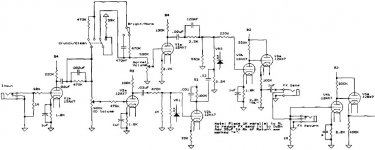
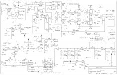
I decided to go with a tube pre and SS power section. After scouring through countless articles and schematics, I found this interesting circuit for the Soldano SLO.
The question is, what exactly are VR1 and VR2? Those parts of the circuit are mentioned in the commentary (second link), but it is unclear to me. I do not know if there is a regulation circuit somewhere, or the LED is just symbolic of what the writer is talking about.

It is first mentioned here: The Third Stage
Any comments would be appreciated.
Thank you.
I decided to go with a tube pre and SS power section. After scouring through countless articles and schematics, I found this interesting circuit for the Soldano SLO.
The question is, what exactly are VR1 and VR2? Those parts of the circuit are mentioned in the commentary (second link), but it is unclear to me. I do not know if there is a regulation circuit somewhere, or the LED is just symbolic of what the writer is talking about.

It is first mentioned here: The Third Stage
Any comments would be appreciated.
Thank you.
The leds are housed along with a cadmium cell that changes resistance with the amount of light. Good for isolation or a simple way to control resistance by some other means.
Thanks. I was afraid of that. Well, it's either try to get the circuit from "sloclone", use a Fender pre, devise my own controls, or otherwise redesign the circuit.
Thanks. I was afraid of that. Well, it's either try to get the circuit from "sloclone", use a Fender pre, devise my own controls, or otherwise redesign the circuit.
You can always wire in a pot of the same value and adjust it manually. What controls the leds?
You can always wire in a pot of the same value and adjust it manually. What controls the leds?
Yes, I am a big fan of slider pots in prototypes. But my knowledge of tube amps is almost non-existent, and why reinvent one of his spokes?
"The AC load consists of a 2.2M resistor in parallel with a 330k resistor and the output impedance Zo of the normal channel's second stage." This is vague.
Perhaps somehow the referred to impedence is translated to the isolator? The amp, in its entirety has been built, and I saw the optos in some pics. Finding info on that site is not fun.
It's coincidental that I already had the idea of using some kind of electronic control with digipots and/or audio switches and a PIC. But this design requires these particular optos in order for the circuit to work.
The two LDRs - VR1,2 - have a high resistance when dark, and they go to a low resistance when lit up by the LEDs. One of them thus shunts the signal to ground when lit, while the other completes a signal path in the other channel. The two LEDs are probably wired in series to operate together. So when they are darl, that one shunt disappears, and the signal path above opens. SO light or dark alternates channels. YOu could replace them with a pair of relay contacts, I suppose.
Thanks. When I checked the price of those LDRs, I sought an alternative. I found essentially the same circuit that uses relays. This is better for me since they can be easily replaced with digital switches, if desired, somewhere down the line. Plus the circuit is easier for me to understand.
But I am not given the HV output number. I have seen several lead amp designs ranging from 300-480v., which I find shocking. What the heck, here it is. Maybe someone could ballpark it.

But I am not given the HV output number. I have seen several lead amp designs ranging from 300-480v., which I find shocking. What the heck, here it is. Maybe someone could ballpark it.

- Status
- This old topic is closed. If you want to reopen this topic, contact a moderator using the "Report Post" button.
- Home
- Live Sound
- Instruments and Amps
- Voltage Regulation (LDR Related)

 Since this is clearly related to guitar amps I have moved it to the proper forum. Please make note of the sub-headers in each forum category to determine whether or not you are posting in the right place. Thank you.