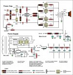
I have a home build amp, similar to the Fender Twin, 4 6L6GC tubes but with a switchable rectifier, bias and high/low option. See my drawing. It's only the power amp, the preamp didn't fit in this chassis and I'm making that separate, but I can still use it like this. And it sounds quite good too.
Specs:
New Electro Harmonix 6L6GC tubes
Plate voltages: 404v
Plate current: 90mA per side of two tubes
Screen voltages: 400v
Screen current: 6-7mA per tube
Bias voltage at this current setting: -26v
Calculating the plate dissipation I get 18.2W.
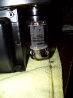
But the plates have a small red spot on them and I can't figure out why at that level of dissipation.
I have set it at 74mA per side with the bias voltage at -35v, plate voltage about 412v and still have the redness. That's the extreme of the bias pots I have. I can go down to -22v but that would clearly be to much current.
What could be causing this red plate issue??
Thanks,
Daniel
Specs:
New Electro Harmonix 6L6GC tubes
Plate voltages: 404v
Plate current: 90mA per side of two tubes
Screen voltages: 400v
Screen current: 6-7mA per tube
Bias voltage at this current setting: -26v
Calculating the plate dissipation I get 18.2W.
But the plates have a small red spot on them and I can't figure out why at that level of dissipation.
I have set it at 74mA per side with the bias voltage at -35v, plate voltage about 412v and still have the redness. That's the extreme of the bias pots I have. I can go down to -22v but that would clearly be to much current.
What could be causing this red plate issue??
Thanks,
Daniel
Attachments
Last edited:
pics
I increased the bias voltage to -41 and the red plating went away. But it measures only 56mA of current for two tubes at 408v on the plates for 11.4W dissipation. Quite low for a 6L6GC.
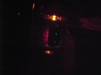
The pics are at -26v bias, 95mA and 389v respectively. And that calculates to 18.5W dissipation...
The flash pic doesn't show the red at all.
I increased the bias voltage to -41 and the red plating went away. But it measures only 56mA of current for two tubes at 408v on the plates for 11.4W dissipation. Quite low for a 6L6GC.
The pics are at -26v bias, 95mA and 389v respectively. And that calculates to 18.5W dissipation...
The flash pic doesn't show the red at all.
Attachments
The red plate is due to too much current.
Or a parasitic oscillation.
You need a scope to see that.
The 6L6 wants to be run in class AB, not class A at this plate voltage... I'd adjust the values of the resistors that go to ground from the bias pots *up* in ohms so you can get more negative voltage on the grids.
The other thing is to drop the screen voltage and current a bit.
As far as I can tell you are pretty close to proper operating voltages and currents, but these are import tubes, and the best thing to do is to adjust them empirically and not rely upon any mfrs specs.
You *do have negative voltage* there? Just checking...
Also, I don't see why you switch bias points AND switch to a cathode bias as well... I guess it does change the tone a bit, but why not just keep the same negative bias and switch in the cathode resistor of appropriate value??
_-_-bear
"What source are you feeding it with?"
It's at idle. Or I plug my guitar directly into it.
"Also, I don't see why you switch bias points AND switch to a cathode bias as well... I guess it does change the tone a bit, but why not just keep the same negative bias and switch in the cathode resistor of appropriate value??"
It's the only way I know to go from fixed bias to cathode bias. It drops the output power a bit and makes the response spongier and loose-more for blues and rock than for jazz or metal playing-as far as I read...
I have not tried it without the NFB, but the circuit I have lets me get to about 0.8%. The Blackface Twin of the 60's has about 12%. Much cleaner and using the pot I can go from 20% to 0.8%-clean to mean...
Last edited:
It looks like you're switching to a combination of cathode bias and fixed bias, yes?
I was just asking why you didn't go with full cathode bias... it's fine that you do this, was just asking what the idea behind it was to not go to full cathode bias... (or whatever ratio you picked)
Regarding the NFB, as you increase the NFB you also drop the gain, so this reduces the effective *drive*, dropping the clipping, so this can account for the change in tone you are hearing. To know how it sounds different you'd want to adjust the input level to match the change in gain so that the peak signal level on the output remained essentially the same... but no matter, as long as it *sounds good* it's fine now.
_-_-bear
OT shunt method can be bogus if the meter has relatively significant resistance itself. Even respected models of meters can have too much internal resistance for accurate results with OT shunt.
Anybody remember the way to use the meter to test the meter for the internal resistance figure?
Anybody remember the way to use the meter to test the meter for the internal resistance figure?
I probably damaged mine. I've had a few 'oh sh$%s' when I forgot to switch the probes and dial back to voltage. Once the fuse blew into pieces of glass. It's a decent meter, a Velleman, so I thought it should be able to handle it. Oh well, I learned now...
And, Gerald Weber swears by the OT shunt method in his books, says the guy who made Trainwreck amps used it-his amps sell for 30K plus now-and this link: Bias FAQ claims "This is the way many pro techs measure plate current."
So that's why I chose this method. I will be using the cathode bias method instead...
If ther are no current sensing resistors between cathode and 0V then I use the voltage drop across half OT primary method. With power off and after PS capacitors have discharged then use your multimeter to measure the resistance of each half of the OT primary, the 2 sides can be signficantly different in resistance. Then with the amp at idle CAREFULLY measure the DC voltage drop across each half primary and the anode current is then easily calculated from Ohms law.
Of-course if it is my own amp I always mod it to have a 1 or 10 Ohm resistor between each cathode and 0V, measuring the voltage across those is always the SAFEST method of determining tube (anode + screen) current.
I have never had much faith in the shunt method, as stated above results can depend upon the internal resistance of the meter.
Cheers,
Ian
Last edited:
With Power OFF and Caps discharged, then measure DC resistance from the primary centre tap of the OT to the anode connection on each side, won't matter which way round the multimeter probes go for these 2 measurements.
Then with amp at idle (no signal) measure the DC voltage drop from OT centre tap (multimeter red lead) to each anode lead (multimeter black lead). CAUTION: both these points are at high voltage even though the voltage difference you will read will likely be only a volt or two (HINT: clip the red lead onto the Centre tap connection before applying power so you are only moving one probe around). Calculate the current in each side by taking the voltage drop for that side divided by the resistance for that side.
Hope this makes sense.
Cheers,
Ian
Last edited:
And just a thought. You have two tubes in parallel on each side, and you are taking measurements that ought to be for two tubes, and you then infer that half of that reading is for each tube. SO 56ma means 28ma per tube.
But the reading alone does not guarantee the two tubes are sharing equally. If for some reason one tube was not conducting fully, its mate might be drawing more current, so the total mighgt look good, but one tube woould red plate while its mate idles along cold.
Not saying it is happening here, but never rule it out. If in doubt, pull one tube at a time and see if you get 28ma for a single tube. (or whatever reading is appropriate.)
- Status
- This old topic is closed. If you want to reopen this topic, contact a moderator using the "Report Post" button.
- Home
- Live Sound
- Instruments and Amps
- Plate current and red plate problem