At last, progress
So today I received the electrolytics I was waiting for from the USA (having bought some cheap Miec, I sought the original fit IC capacitors)
Now Illinois Capacitor cant be that good! By the time UK import VAT is added along with their handling fee, Illinois Caps become boutique. In cost at least.
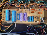
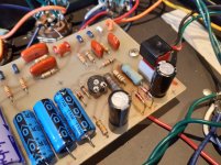
1. 18V zeners replaced with 18V BZX85 1.3W (I have some 5W 1N5343 but I think the lead diameter will be too large for the PCB drill hole)
2. All PSU caps replaced including the low voltage radials (I could almost upgrade these, as the size reduction is quite significant).
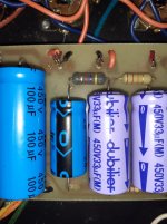
All caps except one I forgot in the preamp circuit (last pic) doh.
That's only 22uF 350V (rather than 500V) so a 500V 22uF Miec will go in there.
The two "warm" 1k6 2W resistors I've left until I get some to replace then with (I planned an order and yes I forgot to order the cheapest items)
So today I received the electrolytics I was waiting for from the USA (having bought some cheap Miec, I sought the original fit IC capacitors)
Now Illinois Capacitor cant be that good! By the time UK import VAT is added along with their handling fee, Illinois Caps become boutique. In cost at least.
1. 18V zeners replaced with 18V BZX85 1.3W (I have some 5W 1N5343 but I think the lead diameter will be too large for the PCB drill hole)
2. All PSU caps replaced including the low voltage radials (I could almost upgrade these, as the size reduction is quite significant).
All caps except one I forgot in the preamp circuit (last pic) doh.
That's only 22uF 350V (rather than 500V) so a 500V 22uF Miec will go in there.
The two "warm" 1k6 2W resistors I've left until I get some to replace then with (I planned an order and yes I forgot to order the cheapest items)
Attachments
Last edited:
Eureka!
I think I have found something amiss after all.
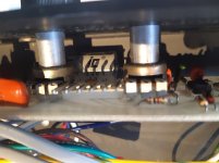
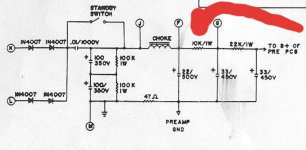
Upon looking at the PSU board, the resistor between "F" and "G" voltage taps, is not the same value as the schematic for the CD120 (posted earlier).
The schematic value is 10k, and lo, I have 4k7.
I initially thought that maybe it was 10k for the CD60 and then 4k7 for the CD120 amplifiers, but I'm not 100%.
Now I dont think it'll do a lot for the higher than usual B+, which maybe due to a replaced power transformer earlier in its life, but it may affect the preamp stages in particular.
I think I have found something amiss after all.
Upon looking at the PSU board, the resistor between "F" and "G" voltage taps, is not the same value as the schematic for the CD120 (posted earlier).
The schematic value is 10k, and lo, I have 4k7.
I initially thought that maybe it was 10k for the CD60 and then 4k7 for the CD120 amplifiers, but I'm not 100%.
Now I dont think it'll do a lot for the higher than usual B+, which maybe due to a replaced power transformer earlier in its life, but it may affect the preamp stages in particular.
Attachments
^ no problem at all!
It really is a fantastic amp, I've played a couple of Marshall JCM models, and a Bassman as guitar amps - the Bassman came close, but the T120R has bested them all, in my opinion.
Typically, it handles clean to bluesy Strat well, as well as nice plump warm Les Paul clean sounds, to a nice thick overdrive.
The reverb is pretty tasty too. If anything, the reverb mix could be higher, as there are times I would like to play with a bit more of a swimming in reverb effect.
A DIYA member, StepheninMelb (if I recall) helped me out with a huge amount of extra detail, when I first set out to restore this amp.
The info is spread over this thread and one other, I believe. The huge amount of info that Stephen input should help with many of the typical component failures, likely suspects etc.
I now use the amp, with a bass cab sporting 4 G10R "greenback" Celestions, and it doesnt want for much!
I just fired the thing back up after a recap, and hopefully I'll get around to rebiasing over the next week, and then give it a good thrashing.
Good luck
Good to read the positive review of yours. Hoping this one will come together without too much fuss.
BTW, mine has the 4.7K 2W in same location in the power rail as yours. I believe that is the stock configuration for the T120-R. Also, the schema calls for 1.6K 2W for the +/-18V rails, mine also has 1.5K 2W and 1.2K 2W in the same locations.
The one I acquired was missing the PT and the OT is/was a Fender Twin Reverb unit dated 8th week of 1976. I removed that as it has only a 4 ohm tap.
The wiring harness for the +/-18V rail and loop send/return and reverb footswitch was butchered. I have the parts on the way to rebuild the harness.
Planning on using 2W zeners and lifting them and the 1.2K/1.5K power resistors up off the board to stave off the thermal decay of the PCB.
Will install F&T caps for the power rails. I installed a Twin Reverb PT in mine using a 1/8" (3.2mm) aluminum plate I fabricated to mount it on. I dismantled the the chassis partially to facilitate making the PT cut-out - I sued the mounting plate as a template. The chassis is fairly flimsy aluminum and why decided to fab the PT mount plate. The end-bell was removed so that I could make the cut-out smaller to add more material around the mounting holes & fender washers were installed on the inside.
I replaced the single secondary OT with the Hammond 1760W as it has 4/8/16 ohm taps - Want to fill all the speaker jack holes.
BTW, I see that yours has a non-stock PT as well. Looking at the chassis mounting point holes and lead thru-holes for the PT, It seems that the PT for these things is much too small for a 100/120W amp. Even the OT looks to be subpar.
The AC outlet jack hole will become an IEC C14 type connector and I will add an internal B+ fuse - Something that should have been included in a 100W amp designed in the late 70's.
Dropbox - 20191103_184925.jpg - Simplify your life
Oooo
That's interesting that the PSU is your amp also has the 4k7 resistor... perhaps I might return it to 4k7 in that case....
The mains xformer in mine is 100% not original. I wondered if it may have been for something like a Twin, being as the voltages are HIGH, and Twiñs are renowned for eating tubes.
The PSU choke, is original, I think. It's very difficult to tell, with little info on the supply, transformers, or choke. And I know little about "other" amplifier iron, so the trail of bread crumbs has disappeared!
I couldn't say if the OPT is original, there arent any extra holes as there are for the mains xformer, and it has all taps.
At the end of the day, this amp wont actually put out 120W, but perhaps the PT failed when tubes shorted, due to lack of fusing.
So yes, a HT fuse is a good shout - I might steal that!
The most annoying thing is the PSU voltages, well over 450V rating of the 2nd set of Caps. I have been looking for a reasonably priced bucking transformer, or 250:230V isolation trafo, to nudge the voltages down all round.
I suspect that the zeners would get hot in 100% stock form, but then, once the PT is replaced and voltages are higher, more current through the whole zener reg circuit, and the things burn up worse than original.
Maybe it would be worth sourcing a replacement PT with lower winding voltages- presuming I can find something suitable.
It would certainly be interesting to see if your example also has uber high supplies too.
Losing the wiring harness is a real bugger though, I'm lucky !
Looking at your picture, both transformers are very different.
The Fender Twin PT is something I saw while I was considering a replacement (after realising it was not original)
Sadly I think the Fender Twin PT is also too hot for this amp, and I've been looking on and off for a suitable replacement with lower voltage windings.
Unfortunately I now suspect mine is a 110/100:380/???isolation transformer
The cooling fan is also different on your example. Mine is 110V and wired to one half of the CT primary.
I reckon mine was modified from a US mains version, to operate on UK mains.
Last edited:
The easiest and cheapest solution (for me)
My plan for sorting out the power transformer issue, is simple - although it has taken me a while to fully work it through.
I will use a 400/415/440: 55-0-55 isolation transformer wired as an Auto transformer to drop mains voltage input down to 220-230Vac input (my mains is consistently 245 - 255V)
I have a suitable 300VA transformer, so all that needs is a switch, fusing and a box.
Still working with amp? Need Bias info please
Hey Everybody!!!
I need to wake this beast.
I don't know where to attach my DMM to get the bias reading.
I have scoured the earth and this one thread has more data than the combined resources of the rest of the planet.
Work done so far:
Replaced the tubes. Then fabricated a riser for the top cover cause tubes were shorter back in the 1900's... I guess. Replaced all electrolytic caps (almost all on the power board were leaking) a couple connectors and then arbitrarily replaced some of the other components. You know... productive tinkering.
It powers up and takes a test tone fine but I didn't want to run it without biasing it.
I'm fixing this for a friend and I have no need for a tube surgeon or bias doctor or whatever hell that thing is.
I really hope you guys are still around. Would love to know how things have turned out.
Hi.
On my T120, there is a 10 Ohm resistor, which you can use to measure mV and from that you know bias mA.
If you look at the underside of the valve sockets, at the left hand nost socket (nearest the power transformer) you will see it, connected from one pin of a socket, to the chassis.
It may not be there, I dont know if it was a addition to my amp, but I would look and check that location.
I havent got around to rebiasing my T120 yet, so I cant really help with expected bias voltage, particularly as I have 7581a installed, not 6L6GC.
I had a replacement power transformer in thisbamp before I owned it, and although I have a simple solution, to provide 220V rather than 240V, I havent got around to building my auto transformer case yet!
I had a replacement power transformer in thisbamp before I owned it, and although I have a simple solution, to provide 220V rather than 240V, I havent got around to building my auto transformer case yet!
Wow. I had no expectations of an answer! Thank you so much!
There is just a jumper to ground so I think can replace it with a 2 watt resistor and use that as my test point.
I can't thank you enough!
After writing last night, one of the power tubes started to red plate. This thing hasn't been turned since it was "declared deceased" 5-6 years ago and all my activity (heating, cooling, flipping etc) has shaken loose another problem. Coupling cap?
But why one tube and not both?
Is it logical and safe and productive to unplug the power tubes and compare V of the pins on each socket?
Serious, I am so excited you guys are still around. Thank you!
Cheers!
They may not be a matched quad of valves, or one may be in it's way out slowly. The bias circuit only controls bias voltage to the quad of valves, so valve tolerances will show through as non equal current sharing by the output stage valves.
I found my amp biased very hot with two different pairs of valves installed, one pair redplated badly.
Since a new set were put in, the red plate is almost gone. Mostly I'd never notice it to be clear, but as my PSU was putting out more volts than the capacitor rating, I knew it would be hot.
Other things to look out for are heat damage to the right hand side of the PSU PCB. The zeners near the bias trimmer, are prone to getting hot, as are nearby resistors.
No doubt this was worsened in my example amplifier, as the voltages were all high. I havent found original voltages, nothing is noted on the drawings that I and others have submitted to this thread.
- Status
- This old topic is closed. If you want to reopen this topic, contact a moderator using the "Report Post" button.
- Home
- Live Sound
- Instruments and Amps
- Dean Markley T120-R fixer-upper project.