Still needs a few screws little tweaking but not too shabby.
You put at lot of work into that and it shows. Very nice.
How does it sound?
Well. not being a guitar player I can not really put it through its paces. But just picking away at the strings a bit I think it is not too bad. Mind you I did not go too far out of standard guitar amp design on this one. The circuit is standard Fender with a few value changes to reflect what is now common to tame an amp that will be distorted. You can look at it as a low voltage single-channel-5E3-Deluxe/cathode-biased-Harvard. Then throw in a Black Face tone stack in a 5 watt package and you are sort of there.
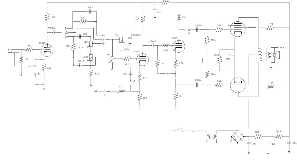
I still want to tweak the values, it can use a drop in the bass when you overdrive it. The three position switch in the front gives you the BF bass-treble position along with the Tweed tone control, then just the Tweed and volume, then the third position the Tweed with a Marshall 470k with a 500pF equalization. Still not enough bass cut to keep it from getting flubby on the bass strings but getting there. I want to reduce the cathode bypass cap on the first stage, maybe 1uF or 0.68uF. All three positions on the rotary switch (used a rotary switch rather than a toggle switch as I originally was going to use going between BF and Tweed as you did not see many toggle switches on the front of radio equipment at the time, the added position gave me the Marshall option) sounds good when clean, the BF tone stack sucks enough gain that it does not get more than a bit of hair on the signal. Mind you this is with a Telecaster, a dual coil pickup would hit it a bit harder. The Tweed positions have a lot more gain and the distortion is pleasing enough but the amount is a function of the bass going through the amp. You can have more gain with the Marshall filtering in.
The NFB switch does an or subtract a bit of gain, does not clean up the tone much, rather it increases the dampening factor of the output and you have a little less sizzle in the top end and on the bottom. I first decided to make the cabinet a sealed enclosure causing me to do the funky chassis in order to have some bass thinking such a small open back enclosure would cancel most of it out. Seems I was wrong, the speaker does not seem to mind (boy life would have been so much simpler not cramming everything in a small spot) but the sealed cabinet does allow the speaker to play louder as the bass is more controlled. No, the amp is not bass heavy, actually it can be twangy (with a Tele, go figure). Just that on a low powered amp/speaker combination you do not have the headroom you have with a larger amp and speaker.
And then there is the speaker out jack. Through a real guitar speaker you have a lot mor volume, boy does it get loud with everything unleashed. I must be getting old because I just tried it at about 8-10' and my ears are ringing. All 5W clean and 8W distorted of Class A power. Would like to run it Class AB but at only 235V getting the tubes biased at 70% they are on all the time. A nice side benefit is that one switch I have disconnects one side of the PI and then you are driving only one output tube in SE. Drops the volume down a decent amount.
It is definitely a bright amp that can be tamed by the tone or treble control. Still need to work on the bass a bit but I do not want to loose it when playing clean. I do need to get another filament transformer as the current one is putting out 11.7V. I am probably going to change out the cathode bypass cap and then button it up and just play it as is. It is more than enough amp to get me going on my R&R career. I'll play with the circuit some more once I get another amp built so I have something to play on rather than sit on the bench. I built a SE amp earlier and asked a one of the guys at work to play through it and let me know how he likes it. He seems to be enjoying it just fine. Oh well, enough reason to trow another one together.
LOL. I wonder what they charge for a big box.
$495 for an F150. They did some speaker boxes for a place that sells to the modified truck crowd, but they told me that it wasn't their regular work and requires a "special setup". Translation...they didn't want to be bothered with one little box.
My amp is dead BTW. It didn't deserve to live so I killed it.
That's what I did to Amp 1.0. It sounded like crap, didn't make more than 1/2 a watt and something seemed to be holding back the sound. I even tried feeding it with a preamp. It still didn't rock. After playing with it for a few days I decided to "execute" it by spinning the power supply knob somewhere north of 300 volts on tubes with a 150 volt maximum plate voltage. It started to sound pretty good right before it smoked and I put it aside for amp 1.1.
Amp 1.0 had 5 tubes. Amp 1.0 had 3. Amp 1.1 sounded pretty good, but didn't quite have enough gain to shred. Hence amp 1.2 which has 4 tubes. It rocked. Amp 1.2 got a few tweaks and became amp 1.3. It was also called Little Big Head. It was he only amp I finished in time for this challenge.
Amp 1.2 original schematic is in post #1021
The revised 1.3 schematic with parts values is in post #1279
The bill of material is in post #1283
The S$#& storm that started in the next post killed everyones enthusiasm for this whole deal.
It's good to see some new life. The person who started this whole thing, and tried hard to kill it, had strong opinions about his definition of what constituted a tube amp. I do not share them. He had a strong adversion to any sand except for maybe the rectifier. Amp 1.3 fit this criteria partly because it was his claims that started this thread.
Well this challenge is over, and I decided that Amp 1.3 could become Amp 1.4. The self split output stage allowed the use of a cheap OPT since the P-P stage remains well balanced. It however limits the power to about 1.5 watts, which fit the challenge, but doesn't rock. I could add another tube for a PI, but I just stuck in a MOSFET PI! The power output went up to about 4 watts and it sounds pretty good. So I got to thinking that it would really rock with a bit more voltage. The bench power supply reveals some real screaming at about 240 volts. How do you get 240 volts from a 120 volt isolation transformer. A bridge gives 160 volts, and a doubler gives 320 volts.....
You invent the SAGULATOR. It is a mosfet based life form with a knob. Turn it one way and you have a stiff zener regulated supply at 240 volts (or whatever you want). Spin it the other way and it drops under load worse than a series resistor. 260 volts at idle 190 at full scream. It makes for some long distorted sustaining notes. It still has some stability issues, but I will post it when I have it working right.
Glad I posted, this is starting to feel fun again. Real interested in your MOSFET PI, I was thinking about using one for an amp I want to build for my nephew.
I forgot. Yes with a 6AT6 in the first hole it just gets a bit of breakup in the signal sucking bass-treble switch position. But put in a 6AV6 (In my case the 12AV6). More than enough gain to get dirty. Changed the cathode cap from 22uF to 1uF on the first triode. Helps out but I am still not sure, the bass is knocked down but it sounds a bit thin. Maybe I should do what is commonly called the Paul C Mod (to the exasperation of Paul C) and change the PI to a fixed bias. I guess I will have to sleep on it.
I forgot. Yes with a 6AT6 in the first hole it just gets a bit of breakup in the signal sucking bass-treble switch position. But put in a 6AV6 (In my case the 12AV6). More than enough gain to get dirty. Changed the cathode cap from 22uF to 1uF on the first triode. Helps out but I am still not sure, the bass is knocked down but it sounds a bit thin. Maybe I should do what is commonly called the Paul C Mod (to the exasperation of Paul C) and change the PI to a fixed bias. I guess I will have to sleep on it.
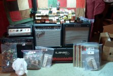
I went to the Orlando hamfest a few weeks ago where I bought 5 dead guitar amps for $5 each.
Whoa!
 You are just trying to make me jealous, I built few amps last year, only one of them got a cabinet (old radio chassis), the rest still naked...
  Love to go to some hamfests soon, may be on my next trip to the States, where are the "big ones" held and when?
 Jaz
Real interested in your MOSFET PI, I was thinking about using one for an amp I want to build for my nephew.
It's real simple. I used the common split load circuit usually populated with a 12AX7 except I put a small TO92 mosfet where the tube should be. I used the LND150 because it biases up not too far from a 12AX7. Don't run more than 1/2 watt through it though. Like a 12AX7 it seems to work good with 1 to 2 mA of current and 100 to 200 volts.
I used the minimum parts version of the PI, the variety where the grid is directly coupled to the preceeding tube. Look at the circuit you just posted. If you have at least 100 volts across the 100K plate load resistor in the first 12AX7 stage, you can try this...Replace the coupling cap to the PI and the 1.2 K cathode resistor with a short. Remove the 1M grid resistor. The PI should still work. Assuming it does, just swap in a mosfet for the 12AX7. It should work. All mosfets seem to sound about the same until they get too big then the capacitance kills off the treble.
This allows the use of one 12AX7 for gain and a mosfet for PI, saves one tube and still has enough gain to shred.
Whoa! You are just trying to make me jealous......Love to go to some hamfests soon, may be on my next trip to the States, where are the "big ones" held and when?
There are local hamfests scattered all over the country usually timed to coincide with reasonable weather since many are outdoors. Here in Florida they are usually in the winter. Further north they are in the spring or early summer. Some are small parking lot shows for a few hours, a few are huge spanning 2 or 3 days.
The three biggest are Orlando, just happened (Home), Ham-Com in Texas on June 8-9 (Ham-Com | The Biggest Hamfest in Texas) and the mother of all hamfests in Dayton Ohio on May 18-20 (Dayton Hamvention). I usually go to Orlando and Dayton but have never been to the Texas show.
See this thread:
http://www.diyaudio.com/forums/tubes-valves/206592-why-do-i-go-hamfests.html?highlight=hamfests
A picture of the Orlando haul:
Attachments
I was concerned with giving the MOSFET too much voltage on the input
I haven't blown it yet and there are two tube stages in front of it in Amp 1.4
If you think about it the split load PI is a cathode (or source) follower with a resistor in the plate (drain) lead. Kirchoff dictates that the cathode and plate currents are equal, since the grid or gate draws no current and there is no other path through the tube. Since the currents are equal and the resistors are the same value, the voltages across them must be the same, we just take the output signal off of opposite ends, so they are out of phase.
This breaks down if you whack it hard enough to draw grid current, or try to drive unequal loads.
The LND150 does not have the usual zener gate protection built it. I haven't blown one yet, but most of my testing has been done with 150 volts of B+ on the preamp. Amp 2.2 runs on 320 volts, and it uses LND150's but not as a PI.
I also use a large gate stopper, 27K carbon comp, since the little critters like to oscillate especially when connected to TV or FM radio tuner tubes. LND150 connected to 26AQ8 = TV jammer big time. It took a 27K to tame them.
There are local hamfests scattered all over the country usually timed to coincide with reasonable weather since many are outdoors. Here in Florida they are usually in the winter. Further north they are in the spring or early summer. Some are small parking lot shows for a few hours, a few are huge spanning 2 or 3 days.
The three biggest are Orlando, just happened (Home), Ham-Com in Texas on June 8-9 (Ham-Com | The Biggest Hamfest in Texas) and the mother of all hamfests in Dayton Ohio on May 18-20 (Dayton Hamvention). I usually go to Orlando and Dayton but have never been to the Texas show.
See this thread:
http://www.diyaudio.com/forums/tubes-valves/206592-why-do-i-go-hamfests.html?highlight=hamfests
A picture of the Orlando haul:
Thanks! Hope to make it to at least one of them in the near future.
Jaz
"Heck maybe I will build one, when's the deadline?"
Hey Globug. We don't need no stinking deadlines.
This thread is too much fun to die.
Will post new schematic soon, and already sketching out next one (which will be inserted into a Kustom BA10 cabinet a friend gave me in disgust).
Cheers
JimG
Hey Globug. We don't need no stinking deadlines.
This thread is too much fun to die.
Will post new schematic soon, and already sketching out next one (which will be inserted into a Kustom BA10 cabinet a friend gave me in disgust).
Cheers
JimG
Normally I have the tube on the schematic, not sure what happened there. I have 12AQ5's, a 12V 6AQ5, and the transformer is a run of the mill 10 watt 70v line transformer. I just want to tweak some capacitor values and try fixed bias on the PI, might even change the screen resistors lower just to hear the effect. The amp sounds good clean, it does have a bit of a problem with too much bass content when you crank everything. I went to a 1.0uF capacitor on the first bypass and it helped. Going to try 4.7nF after the PI.What are the finalized output tubes and the OPT now?
Thanks,
Jaz
This makes me wonder about classic amp designs, and whether "cost saving" options such as using smaller bypass and coupling capacitors contribute to reduced bass response that helps keep the "mud" out when cranked up into distortion. Tone control stacks of course also contribute.Normally I have the tube on the schematic, not sure what happened there. I have 12AQ5's, a 12V 6AQ5, and the transformer is a run of the mill 10 watt 70v line transformer. I just want to tweak some capacitor values and try fixed bias on the PI, might even change the screen resistors lower just to hear the effect. The amp sounds good clean, it does have a bit of a problem with too much bass content when you crank everything. I went to a 1.0uF capacitor on the first bypass and it helped. Going to try 4.7nF after the PI.
And I had to Google that phrase (how did it get called a "stack" only for guitar amps???):
https://www.google.com/search?q=Tone+control+stacks
Every hit looks like a treasure trove. The fifth hit has this interesting offhand analysis:
Earlier Amplifier designs had primitive tone controls ( called "tone stacks") much before the invention of the Baxandall and the parametric / graphic equalisers.
Changing the tone control settings changed the volume
and changing the Bass control also changed the Treble response and vice versa !!
Many tone stacks had a mid frequency hump or depression.
However, guitarists got used to these primitive tone controls and we all grew up listening to the tone created by these primitive early attempts to shape tone.
This makes me wonder about classic amp designs, and whether "cost saving" options such as using smaller bypass and coupling capacitors contribute to reduced bass response that helps keep the "mud" out when cranked up into distortion. Tone control stacks of course also contribute.
And I had to Google that phrase (how did it get called a "stack" only for guitar amps???):
https://www.google.com/search?q=Tone+control+stacks
Every hit looks like a treasure trove. The fifth hit has this interesting offhand analysis:
I do not think it was so much of a cost saving thing as the engineers at the time had a good background in math and the calculations for filtering was known. Then you get a design like the Deluxe 5E3 with coupling caps of 0.1uF and Marshall using 320uF for cathode bypass, both values way in excess of what is needed. The amps at the time were not designed to run into distortion, just a happy turn of events we had musicians setting the amp levels rather than the engineers.
Only two tubes - sustain for days
The single ended 6BL8 output pentode starts clipping - more or less top and bottom - with a peak to peak 2v signal at the grid.
This is achievable with drive set below 4 o'clock and 1st triode out of the signal chain.
I can get happy chords and not too much yelling from the neighbours at this setting.
The 2nd triode clips (grid current) a bit before the output stage if signal is big enough - so switch in 1st triode. This setup gives sustain for days at a range of settings.
Current feedback in first stage is mainly to get the gain down to likable levels - tweak to taste. (The red LED is only an indicator that current is flowing in the tube - handy when prototyping). The other LEDs were selected to set the bias of their respective tubes - they got swapped around a lot during development.
If my wife goes out, and I shut all the doors and windows, the neighbours don't yell (they do go very quiet though).
Through my 12" 96dB speaker I am immersed in the sound but don't need ear plugs.
Yes it is not a single ended trafo but with under 10mA current I haven't detected any signs of saturation with the little 5 watter.
NB: Heresy aside, switchable silicon &/or germanium clipping pairs of diodes at the input of 2nd triode give further range to the tone pallette. Not better, just different (more civilized even), and still endless sustain. Good enough to leave in.
Going to button this one up cos its fun just as it is.
Now for my next trick: Maybe pentode/triode pot (Merlin's version) on input stage, and cathode follower driving the tone stack. Same two tubes cause they are cheap and easy to get.
Cheers,
JimG
Attachments
Five watts is a nice level with a 12", mine is rated for 98dB. One day I will try the LED route.
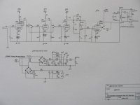
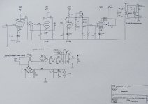
So I am pretty much done with the circuit. I probably could spend hours adjusting the screen voltage, changing the capacitor and resistor values, not going to bother. The amp sounds good enough and does not get too nasty. The output cathode resistor is a 220 ohm, changed the first bypass capacitor to a 1uF and the coupling caps before the output tubes to 0.0068uF. Otherwise the circuit is as the schematic. The resistor value for the preamp filter got cut off, it is a 3.3k. Need a few holes and screws and it should be good to go.
So I am pretty much done with the circuit. I probably could spend hours adjusting the screen voltage, changing the capacitor and resistor values, not going to bother. The amp sounds good enough and does not get too nasty. The output cathode resistor is a 220 ohm, changed the first bypass capacitor to a 1uF and the coupling caps before the output tubes to 0.0068uF. Otherwise the circuit is as the schematic. The resistor value for the preamp filter got cut off, it is a 3.3k. Need a few holes and screws and it should be good to go.
Much better, thanks.Sorry about picture - still struggling with the technology
Normally I have the tube on the schematic, not sure what happened there. I have 12AQ5's, a 12V 6AQ5, and the transformer is a run of the mill 10 watt 70v line transformer. I just want to tweak some capacitor values and try fixed bias on the PI, might even change the screen resistors lower just to hear the effect. The amp sounds good clean, it does have a bit of a problem with too much bass content when you crank everything. I went to a 1.0uF capacitor on the first bypass and it helped. Going to try 4.7nF after the PI.
Thanks, also what is the switch on the plate of the PI for, sorry if this has already been covered before...
Jaz
Now for my next trick: Maybe pentode/triode pot (Merlin's version) on input stage, and cathode follower driving the tone stack. Same two tubes cause they are cheap and easy to get.
Cheers,
JimG
Did you play with the order of the pentode/triode sections? e.g., t->p->t->p, or p->t->p->t... Like the LED bias, must be a nice light show when fired up.
1400 post!!
Jaz
- Home
- Live Sound
- Instruments and Amps
- The Hundred-Buck Amp Challenge