I'm still fighting my cab. For the past week I've been trying to figure out how to mount the chassis now that I've assembled the cabinet.
I should have mounted it before gluing the cabinet!
So, "Aftert-Thought Engineering" was called for help.
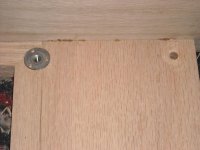
I finally figured a 12" long drill bit would be required. I drilled the four corner holes in the chassis, and a small wooden block that fit the corner. Clamp the wood guide in place, slide drill through it and the chassis to get a perpendicular hole. Four holes drilled.
Next I have to drill a 3/4" countersink and glue in "T" nuts. Now I can start thinking about the chassis layout.
I should have mounted it before gluing the cabinet!
So, "Aftert-Thought Engineering" was called for help.
I finally figured a 12" long drill bit would be required. I drilled the four corner holes in the chassis, and a small wooden block that fit the corner. Clamp the wood guide in place, slide drill through it and the chassis to get a perpendicular hole. Four holes drilled.
Next I have to drill a 3/4" countersink and glue in "T" nuts. Now I can start thinking about the chassis layout.
Haha, great!Curb my enthusiasm? It is good to see that others have gone down the same roads with mixed results. It makes it interesting. It is having to strip my kitchen floor that curbs my enthusiasm.
So you're prestealing my ideas too? I don't have any goal of designing anything particularly new, at least not yet in my solder-slinging career - especially since I'm about 50 years too late to the tube party, and I'm working mainly on guitar stuff at the moment.I have thought I discovered some new tube circuit only to have someone send me a copy of my nifty idea printed in a very old book. I thought I had invented a really cool cathode follower idea until I heard from the holder of the original patent issued in 1957!
I have used this PI / output circuit too, in fact it is in one of my AMP1.0 designs. I have found that it will oscillate if you use a small cathode bypass cap (10 to 25 uF) like typically found in guitar amps AND a crummy OPT (like the Parts Express unit) that has a low frequency roll off and associated phase shift. I didn't come up with that idea either, I found it in a schematic on the web.
I have been told that all possible tube circuits have already been done. I was beginning to believe that until I built a class H design with the plate supply varrying in real time controlled by a DSP. They didn't have DSP's in the vacuum tube glory days.
I checked and it turns out that I did not install a cap across the output tube pair's cathode resistor - so that lowers my chance of oscillation from low frequency phase shift, but also shifts the operating point about. Sounded fine as-is, but I'll try it later with one in to see how it changes the tone (I have some 220uf axial caps around that should do the trick) - thanks for the warning!
scitizen17, I listened to your amp clip this evening - it's pretty tasty, great cleans. Good job!
Also tonight bought chassis and cabinet materials, and found out that 4-40 hardware can be tough to find sometimes...
Thanks for sharing. The variety of approaches in this thread has really expanded my design thinking. I've tried to reciprocate by putting my schematics up as they become viable. (New one coming soon)Ok, cards on the table time.
I'm still fighting my cab. For the past week I've been trying to figure out how to mount the chassis now that I've assembled the cabinet....
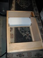
I like to have the chassis slide into the cab like a drawer. I make a kind of rail out of wooden strips. Then I have a wood panel that screws on and keeps the chassis form sliding back out. No mechanical fasteners. The chassis is held on all six sides.
OK, so question time.
I wired it so G2 is fed through a 56K resistor from the second supply capacitor. BUT the power output on continuous sine wave was too low, like 5 watts. I saw on the scope an inverse input signal on G2l, which means that i got negative feedback. So far so good.
I then connected a 47K dropping resistor from the 3rd supply capacitor, which is after a 10K resistor. Less feedback, since G2 supply is now stiffer, power is 10.6 Watts.
The question is: I want g2 to have compression that is progressively heavier, like only on power output peaks, not linear like it is now. What to do?
PS We are talking about a GU50 single ended, with 480V HT and running at 34 W dissipation
I like to have the chassis slide into the cab like a drawer. I make a kind of rail out of wooden strips. Then I have a wood panel that screws on and keeps the chassis form sliding back out. No mechanical fasteners. The chassis is held on all six sides.
That is an interesting idea ChrisA. Unfortunately with the controls up it would require the channel to be vertical. Sliding the chassis down would impinge upon the speaker frame, so the speaker would need to be removed before removing the chassis.
That would probably be a good technique for slope mount controls so I may try that on my next build if I can figure out the clearances for everything.
Mounting vertical with controls up allows me to mount all the tubes vertical down and transformers back. Three sides used for mounting should make layout easier. The downside is there will be a back panel on the top about 8" high. I'll need vent holes, and a mounting plate for the power cord and a fuse holder, etc. I could mount them on the chassis but access would be restricted.
Haha, great!
scitizen17, I listened to your amp clip this evening - it's pretty tasty, great cleans. Good job!
I'm going to do some playing and recording on Friday BUT I shiver with dread at the possibility of getting positive reviews. I'd rather not post my clips if that's going to be the case. Positive reviews are BORING. OTOH the destructive force of extremely negative reviews could get me down and impair my musical career. LOL. To be or not to be....she loves me, she loves me not.
So you're prestealing my ideas too?
Yeah, I stole it, but.....I put it back! I have abandoned the connection from the plate of one output tube to the grid of the second. I am now using a self split arangement with a 150 ohm shared cathode resistor and no bypass cap.
I experimented with "your circuit" because the ultra simple design (about $40 total amp parts cost) didn't have enough gain. The plate to grid connection did bring up the gain but I didn't like the sound, and there still wasn't enough gain for overdriven distortion. I have decided to add another tube to really boost the gain. So now my $40 amp is a $45 amp. That design is being built now and I will post the schematic if it works.
Remember how this thread got started. An Ebay seller of a $69 tube guitar amp kit posted info about his kit in a few threads asking for ideas and circuits for low cost guitar amps. He stated:
The lowest cost guitar amp on the planet.....Only 69.95 COMPLETE! (Except for the speaker and the chassis)...... You can't build a guitar amp for less than this. Not no way. Not no how.
I replied:
Wanna bet? Sounds like a challenge to me. Anyone else? What kind of guitar amp can you build for $69.95?
The OP of one of the threads started this challenge with his $100 criteria which brought some criticizm from the Ebay seller. Most of the posters here have been working towards that goal. I have been working on the best amp that I can make for $99.999999 too.
I decided that since I was the person to say the 2 words that started this, I would also work on an amp that would fit into the $69.95 criteria. The OP declined to publish any info on his design, but we know it uses a 6EB8. I wired a 6EB8 up as a triode gain stage, pentode output stage using a typical guitar amp circuit and played with it. It can be built rather cheaply but there just isn't enough gain.
My $40 three tube circuit works much like the 6EB8 circuit and fulfils my "so simple that even a drummer can build it" criteria. Both designs however do not have enough gain for super overdriven distortion without an external pedal. The 4 tube design has not yet been tested, so we will see......
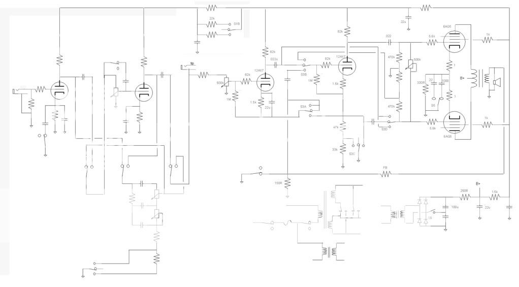
A little farther from the $100 limit again, replied to another discussion and did a copy and paste of a couple schematics coming up with a composite of two designs. Circuit needs to be cleaned up but just wanted to show the general idea. Should be familiar from my previous schematics but a quick rundown.
Switch for tone stack, three position double pole. BF Bass/Treble with 22uF first stage bypassed, less mid cut no bypass, tone stack disconnected.
Three pole two position switch, puts tone stack between first and second triodes (clean Fender) or after second triode (Bassman style, sorry no cathode follower but might go Mosfet at some point).
Preamp B+ voltage switch. Lower voltages as earlier amps or higher for more cleans.
Four pole three position switch, Changes the two triodes from cathodyne, long-tail pair, and paraphase inverter.
Switch for feedback.
Switch shown for increasing output tube cathode capacitance but could quite easily go to fixed bias instead.
I'll find out how viable some of these are on the current builds I am doing, eventually want to add reverb also.
The 6EB8 does have quite enough gain to produce useful bluesy overdrive distortion.
The triode has an AF of 100. The pentode has a mu of 12,000.
If you're going to use a cheap output transformer, you need to use the right cheap output transformer.
First stage operating point, interstage loading, screen voltage and bypass, pentode bias voltage, all of these are critical to getting the desired result.
It has been done.
There are many people who know that the gain of a 6EB8 produces quite useful and satisfying distortion. It isn't a stand-alone Fuzz Face, it isn't a Big Muff Pi, it isn't a Rat. It won't get you into heavy metal all by itself.
But it is a stand-alone practice amp with the "right" amount of volume and distortion.
It will get you into some pretty heavy Blues with a standard single coil pickup.
Not much into heavy distortion, more inclined to the edge of breakup or rock tones. Mind you ACDC and the Ramones can be a lot of fun, a pedal with boost might be in order. Not being familiar with the tube I would be interested hearing some clips of it.The 6EB8 does have quite enough gain to produce useful bluesy overdrive distortion.
The triode has an AF of 100. The pentode has a mu of 12,000.
If you're going to use a cheap output transformer, you need to use the right cheap output transformer.
First stage operating point, interstage loading, screen voltage and bypass, pentode bias voltage, all of these are critical to getting the desired result.
It has been done.
There are many people who know that the gain of a 6EB8 produces quite useful and satisfying distortion. It isn't a stand-alone Fuzz Face, it isn't a Big Muff Pi, it isn't a Rat. It won't get you into heavy metal all by itself.
But it is a stand-alone practice amp with the "right" amount of volume and distortion.
It will get you into some pretty heavy Blues with a standard single coil pickup.
Hi Printer,
This was not a reply to your post, but to others.
And forgive me, but I meant to say ". . . has a gm of 12,000 . . ."
I do understand the difference between transconductance (gm) and amplification factor (mu).
Although it is classified as a sharp cutoff pentode, an examination of its graph of grid voltage vs. transconductance and plate current will show significant differences between the amount of gain obtainable at various operating points.
In fact, the maximum gm of this pentode goes all the way up past 16,000 before reaching saturation.
An audio clip is on the to-do list, but not available yet. I need to rehearse some rust out of my fingers first.
I could just bang on the strings to prove my point, but it wouldn't be very elegant.
I am at work from 8 AM to about 7 PM every week day. Computer use is monitored and forum posting is frowned upon. In my last post I attempted to correct some incorrect statements another poster made about something I said, and provide some information about the 4 tube version of AMP1.0 now called AMP1.2. It took me about 20 minutes to compose and type my post into a cell phone and the moderator about 20 seconds to delete it. I do not have 20 minutes to waste during my work day, so I will refrain from posting until I have something important to contribute and a real unmonitored computer to do it from. This will be rather infrequent for the next 3 or 4 weeks.
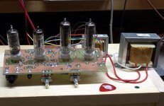
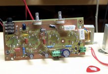
AMP 1.2 is alive and working. Power output is 2 watts when the controls are set for a clean undistorted output. Power output is just over 3 watts at full crank. There are two controls volume, and tone / distortion. The tone / distortion control can provide a wide wange of sounds from clean to cranked. No you aren't going to get a full metal racket from a 2 watt amp, but I did manage to get some acoustic feedback with the guitar about 6 inches in front of the speaker. Total parts cost is less than $50.
AMP 1.2 is alive and working. Power output is 2 watts when the controls are set for a clean undistorted output. Power output is just over 3 watts at full crank. There are two controls volume, and tone / distortion. The tone / distortion control can provide a wide wange of sounds from clean to cranked. No you aren't going to get a full metal racket from a 2 watt amp, but I did manage to get some acoustic feedback with the guitar about 6 inches in front of the speaker. Total parts cost is less than $50.
Attachments
That is an interesting idea ChrisA. Unfortunately with the controls up it would require the channel to be vertical. Sliding the chassis down would impinge upon the speaker frame, so the speaker would need to be removed before removing the chassis.
I've used this method on "controls up" amps too. Look at the Fender Baseman, Champ of any of the tweed era amps. They use a cut out on the top panel. I do it just like Fender did except I place a pair of small wood blocks under the chassis.
You can see in this photo (50's vintage 5F1) that Fender used two machine screws from the top. But I like to add a pair of wood blocks under the chassis and glued to the cabinet sides. Heuse wood for the top plate that was thick enough that one could set the amp upside down on the floor and not damage the controls
http://myfenderchamp.com/wp-content/uploads/2011/07/IMG_9300.jpg
I am at work from 8 AM to about 7 PM every week day.
Man, that's a lot.
It took me about 20 minutes to compose and type my post into a cell phone and the moderator about 20 seconds to delete it. I do not have 20 minutes to waste during my work day,
Now you're talking. Moderators panic easily, not a funny job to be a chaperone. It's just an observation - I'm not annoyed at them.
Well, last Friday I did try out some cheap speakers ( a Celestion, a Beyma and some vintage ones with alnico magnets) and I also did some recordings. Pretty disappointed with the final results. Clips need editing, it just doesn't sound right. I was pretty happy with the live sound though and I've found out that the secret lies in the OPT and speaker combo. Different amp designs don't make that much of a difference. I'm busy with others things so I won't be contributing here much either. I'm curious about the one tube amp (tubekit) and maybe I will buy that tube to check it out.
I could see why they did some editing. Already it is a hundred page thread (does that mean the value is increasing, less than a buck a page) more or less on topic. Doubt things could disintegrate to the point of some of the topics I oversaw on another site (trying to back out of my obligations there so I can play more with this guitar thing).
Now rather than empty content in this post, thought I would share a simple Champ type circuit I want to build. The output tube/transformer could be whatever turns your crank, the interesting little bit is the tone control. A DPDT switch can give you the option of having the tone control between the first and second stage or between the second and the output tube. I did the Master volume like a Fender 5E3, rather than as a voltage divider to decrease the signal to the power tube it loads down the second stage and most likely screws around with the frequency response. To give it some more complexity it is inside the feedback loop more than likely messing things up some more. The transition where the feedback runs out of gain might make for some interesting sounds.
The part values are a starting point for now, maybe get to assembling it tonight. Looks like the kitchen is going to be a bigger job than I expected (mind you that is probably why I have not tackled it before now), it is getting in the way of me playing.
Deja Vu all over again
Don't know anything about your kitchen project, but those words have a familiar ring for some reason.
I seem to remember someone having said (or having tried to suggest) something like that about Topic 1 way back at the source of this 100+ page thread.
The pronoun was different, though.
going to be a bigger job than I expected
Don't know anything about your kitchen project, but those words have a familiar ring for some reason.
I seem to remember someone having said (or having tried to suggest) something like that about Topic 1 way back at the source of this 100+ page thread.
The pronoun was different, though.
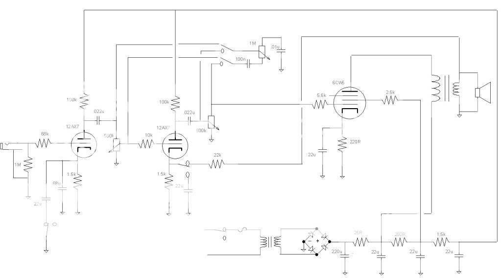
Tubekit's Amp Schematics
Don't know what happens to business after giving this away, since I don't make circuit boards, just create a margin by buying wholesale, but I once said I would submit this, and I keep my word.
This is the revised amp, for international use. It's "beefier" than the original because of higher plate voltages.
It works as claimed--here and elsewhere.
Don't know anything about your kitchen project, but those words have a familiar ring for some reason.
Oh you have asbestos also?

- Home
- Live Sound
- Instruments and Amps
- The Hundred-Buck Amp Challenge