Hi Vintage Guitar Amp Fans,
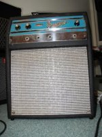
I picked up an old Supro S6616 from Craigslist for a friend in an other state. (1965)
The Tremolo works but it is stuck on one speed, so I told him I would fix it before shipping it to him. The Pot/SPST Switch has been changed but it tests fine. It is a 500K and it is a Linear Taper and its values change appropriately across the rotation. The amp is point to point wired so I traced all the wires from the Pot/Switch to the corresponding component. All in order. I also checked every value on all the resistors and caps in the Tremolo circuit, all within spec. I would think if there was anything wrong with the 12AX7, the whole circuit wouldn't work.
The schematic shows a 500 ohm pot but all the other Supro amps with the same circuit (especially the S6622), all show a 500K pot for speed in the Tremolo circuit.
Here is a resource for Vintage Amp Schematics to see: http://www.schematicheaven.com/bargainbin.htm
If you want to see the schematic, unfortunately it is too large to load here so please use the above hyperlink to see the S6616 and S6622
Anybody have any Ideas? I would be Eternally Grateful!
Regards//Keith
BTW, Hi to all of you who I haven't seen in a while! (sorry, playing guitar, of course)
I agree, it's obviously a 500K pot - and there's almost nothing that could cause it not to work. Basically there's the pot, the 100K resistor in series with it, or the connections to them both.
Check with an ohmmeter from where the 100K meets the .03 and .01 (actually test from one of the capacitors) down to chassis. As you vary the control the resistance should change between 100K and 600K.
Check with an ohmmeter from where the 100K meets the .03 and .01 (actually test from one of the capacitors) down to chassis. As you vary the control the resistance should change between 100K and 600K.
Nigel Goodwin said:I agree, it's obviously a 500K pot - and there's almost nothing that could cause it not to work. Basically there's the pot, the 100K resistor in series with it, or the connections to them both.
Check with an ohmmeter from where the 100K meets the .03 and .01 (actually test from one of the capacitors) down to chassis. As you vary the control the resistance should change between 100K and 600K.
Hi Nigel,
Now this is funny (not really). If I test from the ground (wiper) to where the pot connects to the 100K resistor I get from 1.9K to 490K. Then I go to the other side of the 100K resistor and all I get is 104K. The actual value on the resistor is 104K, so even going through the pot and the resistor, all I get is the value of the resistor. But the pot by itself reads fine when standing alone across its range.
?????? It Boggles my MIND!
Thanks for your help!
Regards//Keith
One probe to ground (chassis), the other to the far side of the 100K resistor, 104K. When I jump over the 100K resistor to the wire that runs to the outer lug on the pot, at that moment, 403K. every time I moved the pot to a new value, it changed on the lug wire. When I jump across the 100K resistor in series with nothing in between, always 104K.
Freaky?????????
The sum of the parts add up to less in this situation!
In fact, always 104K when in series regardless of what the value is on the pot.
Thanks!
Regards//Keith
Freaky?????????
The sum of the parts add up to less in this situation!
In fact, always 104K when in series regardless of what the value is on the pot.
Thanks!
Regards//Keith
So just to eliminate a variable and be sure, I went to RS and bought a 500K pot as a test device.
Sure enough, after the change, measuring from ground to the far side of the 100K pot, I get from 104K to 580K.
Who would ever think. The pot in a stand alone test tests fine but in series acts like a piece of wire.
Maybe the wattage was too low????? but when tested with a piece of test equipment in series doesn't stress it?
That answer is done! Now to find an appropriate pot/switch for this 44 year old amp hopefully with the correct knob.
One last question:
Us Yanks use 120 Volts AC. This amp came with a 2 prong/wire AC plug. I want to use a 3 prong/wire setup with ground to lessen the chance of hum, this is what I think is the right configuration (want to be sure on this vintage stuff). Ground to chassis, Neutral to fuse side and Hot to switch side!
Any thoughts on that format?
Thanks Nigel!
 Pints to you for bringing me to the next level thought on troubleshooting! I was stumped!
Regards//Keith
Sure enough, after the change, measuring from ground to the far side of the 100K pot, I get from 104K to 580K.
Who would ever think. The pot in a stand alone test tests fine but in series acts like a piece of wire.
Maybe the wattage was too low????? but when tested with a piece of test equipment in series doesn't stress it?
That answer is done! Now to find an appropriate pot/switch for this 44 year old amp hopefully with the correct knob.
One last question:
Us Yanks use 120 Volts AC. This amp came with a 2 prong/wire AC plug. I want to use a 3 prong/wire setup with ground to lessen the chance of hum, this is what I think is the right configuration (want to be sure on this vintage stuff). Ground to chassis, Neutral to fuse side and Hot to switch side!
Any thoughts on that format?
Thanks Nigel!
Pints to you for bringing me to the next level thought on troubleshooting! I was stumped!Regards//Keith
KP11520 said:Us Yanks use 120 Volts AC. This amp came with a 2 prong/wire AC plug. I want to use a 3 prong/wire setup with ground to lessen the chance of hum, this is what I think is the right configuration (want to be sure on this vintage stuff). Ground to chassis, Neutral to fuse side and Hot to switch side!
Any thoughts on that format?
Yes, that's sounds fine - although personally I'd like to see the fuse as well as the switch in the live (hot) side (for that matter I'd like to see a double-pole switch). Perhaps it's done that way because it's a non-polarised plug?.
All UK sockets are three pin, earthed, and have a fused plug - it's been that way for decades now - although preceding that there where many different types of plugs, both two and three pin.
KP11520 said:[B
. Ground to chassis, Neutral to fuse side and Hot to switch side!
Any thoughts on that format?
[/B]
I always put the fuse in the hot line, before the power switch. This seems to be the common commercial practice as well. (Check out some schems at schematicheaven for commercial samples, if you haven't found your way there already.)That way, if the fuse blows, you don't have anything 'live' on the chassis beyond the fuse holder. With the fuse in the neutral (white) line, the chassis (and the guitar plugged into it) could be hot even after the fuse blew (assuming that the breaker in the household/venue didn't trip.)
Cheers
John
PS (edit) While you are at it, I'd consider replacing the .01 cap that's across the AC line with a new X2 type cap X2 'Safety' Caps (or eliminating it altogether).
Thank you both for making me aware of better ways to make 44 year old technology safer.
Funny thing is that .01 Ceramic Disk cap that the schematic shows across the AC line is actually between (before) the fuse to the chassis.
Any thoughts on handling that if I put the Hot side through the fuse? Leave it there or replace it with a safety cap or move it to the Neutral side or with a safety cap there or a safety cap on both (hot and neutral) to chassis ground or lose it and put a safety cap between Hot and Neutral?
I might as well get this right!
Thanks fellas!
Regards//Keith
Keith-
That .01 uF cap is there to filter out/bleed off to ground high frequency noise ( like radio stations, and line noise from dimmer switches, etc).
If I'm going to use them at all, I generally put in two caps, one from each AC leg (black,white) to a solder lug at the chassis ground point where the green (or grn/yell) wire attaches.
On a newer (or newly-built) amp with an IEC (computer-style) receptacle for the line cord, the caps can be soldered right on the chassis connector. On a vintage amp, you may have to 'look around' a bit to find secure soldering points. Though you see a lot of 'hanging connections' (solder joints in mid-air) in diy pics, it's not a good idea. Even if you have to put in a short lug strip (on one of the power transformer bolts?), it's wise to find secure anchoring points for all connections.
Cheers
John
Hi John,
I have seen the two caps from each leg to chassis ground before and That is what I think is appropriate but after reading about the Safety Caps, that looks like a better idea. I guess designers have learned a thing or two over the past 44 years!
I don't want my friend to have too many beers while playing his electric guitar outside and have a bathroom accident just as something shorts out in the amp!
He couldn't live with himself after that! LOL
Thank you for the refinement kelp of bringing this amp "up to date" safely while respecting its vintage status!
Cheers to you too! 
Regards//Keith
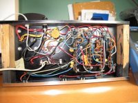
BTW, attached is a photo of the undersideof the chassis
I have seen the two caps from each leg to chassis ground before and That is what I think is appropriate but after reading about the Safety Caps, that looks like a better idea. I guess designers have learned a thing or two over the past 44 years!
I don't want my friend to have too many beers while playing his electric guitar outside and have a bathroom accident just as something shorts out in the amp!
He couldn't live with himself after that! LOL
Thank you for the refinement kelp of bringing this amp "up to date" safely while respecting its vintage status!
Cheers to you too!
Regards//Keith
BTW, attached is a photo of the undersideof the chassis
Attachments
Keith-
It looks like one of the PT bolts would be a good spot for a terminal (solder lug) strip if you have one handy. Then you could terminate the line cord there, solder in your caps, and carry the wiring along to the fuse/switch, etc. And no visible alteration to the chassis.
A 15 cent terminal strip is always a good excuse for another electronics order! ;-). (Steve at apexjr had some the last time I looked. Otherwise, the usual (tube) suspects will surely fix you up....)
Sometimes the hole in the lug strip needs to be drilled/reamed out a bit to fit the #10? PT bolt. Be sure to use a good star washer and extra nut.
John
Attachments
Hi John,
With the new cord entering the chassis right there, that is a great idea... No added hole drilling to mount a strip! I am sure I can find something like you have pictured. I have to order the Pot, Power Cord (16/3) and some sort of chassis clamp (is that what they call them?) for the cord, two Safety caps and a small terminal strip anyway, so why not make it one big order. That is if I can find a similar pot to the original. That is a 500K Rotary Linear Taper Pot with a rotary SPST switch (not push/pull or push button) and 1/4" threaded sleeve by 3/8" split nylon shaft, at the same place that has the rest!
Wish me luck!
Thanks again!
Regards//Keith
Hi John,
I have 2 questions if you are still watching.
I did all that was suggested.
I used two Y2 safety Caps as Just Radios suggested for line to ground connections. I also used the same value of the Ceramic Disk Cap I removed, .01uf. Hopefully that is OK or was I supposed to divide that to .005uf X 2?
BTW, what happens as you change these values?
Also when adding a ground to chassis, did it matter which side I chose to become Hot or Neutral? (I removed the old 2 wire cord and non polarized plug and replaced it with a 16/3 with a ground) I used the side with the switch (see schematic) to be Hot and moved the fuse to before the switch and put the caps at the points (and to ground) where the power cord wires are first soldered to anything in the amp.
Here is the schematic: http://www.schematicheaven.com/bargainbin/supro_s6616.pdf
It's done and everything works as it should but I just appreciate a more experienced set of eyes checking my work!
Thanks Again!!!
Regards//Keith
Hi, Keith-
Sounds like you 'did the right thing' with your amp project.
Those caps on the AC lines are just for filtering out high frequency junk/static/local radio station that can be on AC lines from dimmer switches and such. The caps look like a direct short to high frequency signals, but keep the 60Hz chugging along the rails.
Putting the fuse and switch on the hot line is considered best these days, though I've seen quite a few older amps with 'one on each'- mostly for convenience in finding solder points, I think.
You've done a good thing for the amp and now can feel better about some kid plugging in to it- it's a lot safer than it was.
Cheers
John

- Status
- This old topic is closed. If you want to reopen this topic, contact a moderator using the "Report Post" button.
- Home
- Live Sound
- Instruments and Amps
- Supro S6616 Trojan Tremolo Help 1965