Hello I have a problem with newly built aussieamp. These are the the old nxv300 modules, they have been laying around for some time. I'm using buffalo32s as source (with volume controller). The problem is that when I hook up the buffalo (either rca or xlr) I get some sort of buzz in the speakers. And even stranger, with the volume all down, I still get music through the speakers. The buffalo I've used before and never had any problem. The buffalo is not grounded.
Last edited:
Hello I have a problem with newly built aussieamp. These are the the old nxv300 modules, they have been laying around for some time. I'm using buffalo32s as source (with volume controller). The problem is that when I hook up the buffalo (either rca or xlr) I get some sort of buzz in the speakers. And even stranger, with the volume all down, I still get music through the speakers. The buffalo I've used before and never had any problem. The buffalo is not grounded.
Hi Mesc
Do you have the nxV300 power supply grounded to mains chassis earth?
cheers
Anthony
Yes I have. I have been experimenting some more, and, this is what I found. I tried different sources. Sound card rca out: This one also produces significant buzz when connected. Tested the buffalo on some headpones, it seems the volume issue remains there as well. So I guess somehow the buffalo has changed, probably something I've done with the configuration. Now I'm playing music with a small mp3 player as source, and a homebuilt cmoy as preamp. There is some buzz with that one too, but less than the other options.
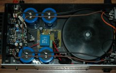
Here's a picture. mains earth is connected to chassis right where it enters. I've seen this recommended as far as I remember. But will there be loop problem with these two seperate connections?
Also I should mention, with the current setup the sound is more of whoosh now than buzz. (with the cmoy peamp)
Edit: Oh yes. underneath the nxv300 is a peaker protect board. Ive soldered speak-pos underneath the board
Also I should mention, with the current setup the sound is more of whoosh now than buzz. (with the cmoy peamp)
Edit: Oh yes. underneath the nxv300 is a peaker protect board. Ive soldered speak-pos underneath the board
Attachments
Last edited:
Ok if we disregard everything but the whoosh now. Because I think maybe the buzz might be some computer noise.
When the amp is not connected to any source, there is whoosh. When connected to the cmoy there is whoosh with slight buzz..
So I guess the problem to focus on is idle whoosh noise in my amp. Of course I would like it to be as silent as possible. So, Im looking to solve this somehow. I know its possible to have silent nxv300, I just want to know what I might have done wrong.
From your photo it looks like you have connected to chassis via the loudspeaker
GND return is that correct?
If so it would be best to undo this and wire it directly to the loudspeaker
terminal. Ideally the power supply Power ground should be connected to
the mains earth right at the point on the chassis where mains Earth is connected to the Chassis earth point.
This way you are not relying on the chassis case to provide an earth return to the mains chassis earth connection point.
With the input shorted do you get any noise coming from the loudspeaker?
If so at what distance can you hear this sound?
Cheers
Anthony
I have rearranged the grounding, except the main earth connection which still is by itself on the other end.
There is no difference. Maybe its normal, I'm not sure, but its not my idea of dead silent.
About the grounding as seen in the picture, is it ok to have it like that, or shouldn't it be like that regardless?
It was kind of easier/tidier like that.
There is no difference. Maybe its normal, I'm not sure, but its not my idea of dead silent.
About the grounding as seen in the picture, is it ok to have it like that, or shouldn't it be like that regardless?
It was kind of easier/tidier like that.
The woosh sound I assume is actually hiss, a small amount coming
from the tweeter with your ear up to it is quite normal for this amplifier.
You could leave the grounding arrangement, what you may need to do is to
connect a ground wire from the Cmoy pre-amp GND point to the power amplifier power GND, this should help with the buzzing noise and will equalise the GNDs between the to units, rather than it trying to happen through the signal GND.
The same can be done between the Computer case and Power amp mains GND point.
Anthony")
from the tweeter with your ear up to it is quite normal for this amplifier.
You could leave the grounding arrangement, what you may need to do is to
connect a ground wire from the Cmoy pre-amp GND point to the power amplifier power GND, this should help with the buzzing noise and will equalise the GNDs between the to units, rather than it trying to happen through the signal GND.
The same can be done between the Computer case and Power amp mains GND point.
Anthony
Hello again
This project has been in stasis for some time now. I now have a nice opportunity to finish.
I have done some improvements in wiring (making it safer), and also played some music, and I like it very much.
When using my battery powered Objective2 as pre with small mp3 player as source, there is no unusual hiss. I'm confident its normal and I'm happy
But... there is that issue with grounding of source or pre, and it creates problems. I suppose its a typical green diy'ers problem. Ground loop something.
Your last post mentions making connections between the other appliances, but wouldn't that be the same as a typical grounded electronic equipment, except maybe the ground goes into the wall and everywhere?
Also, it sound strange to me to have a separate wire going between my hifi equipment, never seen that before
Hopefully I can learn to tame this ground hog once and for all.
-steoll
Hello
I'm practically finished with both my amps now, and I'm NOT dissapointed anymore (couldn't remove the "thread icon").
Very happy in fact. There isn't any noise hum/whatever anymore, it was the other equipments fault.
Though I am starting to regret going xlr. I was thinking of adding an rca input but I'm not sure how to implement it. When RCA in, should "-" and "gnd" be shorted? How best have both options?
Thanks for the good amp
I have "updated" an old amp and added xlr inputs.
Pin1 to Chassis.
Pin2 to +IN of amp
Pin3 to -IN of amp, which also happens to be Signal Ground.
I added 47pF from 1to2 and from 2to3 and from 3to1. That effectively gives me differential mode RF filtering and common mode RF filtering on the input right next to Chassis so that it is effective to VHF.
I have conventional RF and DC block filtering at the amp PCB.
I had been planning to do this to a variety of my amps. I've started.
I did enquire a few weeks ago about this but got no useful replies.
Today, I found it in Ott page603 fig15.16a
Earlier he had stated that the inherent inductance in the cable/s was sufficient to make these "at Chassis" filters effective.
Hi
Great to hear your amp is working well now.
To unbalance the input of the nxV300 amp
Short the inverting input to signal ground and connect the + input to the RCA.
Cheers
Anthony
Yes I suspected as much. But was thinking about having both options. Would I need a switch to select between xlr and rca?
I tried using a "xrl - rca" cable before. The cable internally shorts pin1 and 3 so I thought i would be ok but it didn't work..? I was thinking it had to do with my input caps, I have one on both "+" and "-". So it would probably have to be shorted after the caps, at the board.
Is that right btw, to have two dc caps in xlr?
I have "updated" an old amp and added xlr inputs.
Pin1 to Chassis.
Pin2 to +IN of amp
Pin3 to -IN of amp, which also happens to be Signal Ground.
I added 47pF from 1to2 and from 2to3 and from 3to1. That effectively gives me differential mode RF filtering and common mode RF filtering on the input right next to Chassis so that it is effective to VHF.
I have conventional RF and DC block filtering at the amp PCB.
I had been planning to do this to a variety of my amps. I've started.
I did enquire a few weeks ago about this but got no useful replies.
Today, I found it in Ott page603 fig15.16a
Earlier he had stated that the inherent inductance in the cable/s was sufficient to make these "at Chassis" filters effective.
Interesting, though not sure I need filtering, would it help with ground loopish problems? Did you use ordinary cheap ceramics?
Ceramics are probably the most effective @ vhf and beyond. So, yes.
Some Balanced Sources will plug straight into the XLR arrangement I have described.
Some will benefit from adding a resistor into the cable feeding Pin3.
I wonder if there are some Source types that are not compatible with my arrangement?
Any help forthcoming?
Some Balanced Sources will plug straight into the XLR arrangement I have described.
Some will benefit from adding a resistor into the cable feeding Pin3.
I wonder if there are some Source types that are not compatible with my arrangement?
Any help forthcoming?
Some Balanced Sources will plug straight into the XLR arrangement I have described.
Some will benefit from adding a resistor into the cable feeding Pin3.
Was you amp not designed for xlr input?
My connections are as yours, except I don't connect pin1 to chassis directly. Pin1-2-3 are connected to the corresponding 3 pins on Anthony's modules, and I find that the gnd (pin1) pin is connected through to chassis ground.
No, I have just one balanced Source and will be building some balanced Power Amps soon.
I want them all to be compatible.
The XLR addition will allow a balanced input to be inserted between the XLR and the unbalanced Power Amplifiers. I can use a balanced input transformer (I have 6 from a previous Group Buy) for very long cables, or I can use Cordell's jFet based bal to unbal active circuit.
PIN1 MUST be connected to CHASSIS right next to the input socket, by the best RF connection.
PIN1 MUST NOT go via a torturous route to PCB and then on to Chassis.
no.Was you amp not designed for xlr input?..........
I have "updated" an old amp and added xlr inputs.
There is no need to ground the PSU Zero Volts at the same point as the PE wire is connected to the Chassis.
Normally we expect to see the PE wire connected to Chassis very close to the incoming mains cable using a short wire connection.
The PSU Zero Volts can be connected to Chassis anywhere else that is convenient to the Circuit. The Ground Plane effect of the Chassis will ensure that any Fault Current will find the lowest impedance route back to the mains distribution board via the PE wire.
Artificially increasing the impedance of the Return Path for the Fault Current will INCREASE the voltage of the Zero Volts with reference to Ground during the Fault incident. Using a wire connection from PSU Zero Volts back to the mains PE connection to Chassis must, almost by design, result in a higher impedance.
- Status
- This old topic is closed. If you want to reopen this topic, contact a moderator using the "Report Post" button.
- Home
- Holton Precision Audio
- nxv300 build