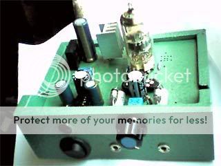
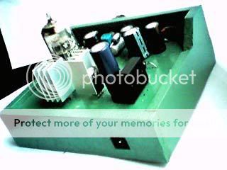
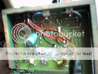
I have posted a picture or 2 in another thread, but I have only just completed the documentation to go with the project.
It is available at http://www.head-fi.org/forums/showthread.php?p=2764048


It is available at http://www.head-fi.org/forums/showthread.php?p=2764048


Attachments
Nordic,
I'd really like to build this puppy. I built a CMOY and liked it, then a Meta42, also liked it, but it is quite fatiguing with my Grados. I expect that some tube-warmth would help tremendously.
What sort of life expectancy would you expect a regular 9V battery to deliver? Presumably, the amp could be run with a 9V walwart, couldn't it? Are PCB's available, or is it "make-your-own" or point-2-point?
Charlie
It needs both, the 9V batteries power the cathodes, and draw so little current they will last for a very long time.
However the heater also needs alot of power +_6V at 365mA = 2VA. So, you do need a walwart (in which case remove the rectifier) or transformer capable of producing about 12V- 20V which gets fed into the LM317 which in turn then is set to 9V... the HV supply or B+.
The opamp also gets its power from this rail, but that is less than 100mA at max and about 10mA at idle. So if you use a walwart get something that can do about 1000mA or it will get plenty hot.
It sounds very good, MUCH BETTER THAN A CMOY, I am using an NE5322 opamp at the moment. On power it on, you will first hear nothing, then alot of soft humming, and then the music breaks through and the hum becomes almost imperceptable even during quiet pieces. VERY IMPORTANT TO DO ALOT OF BYPASSING BECAUSE OF THE MINIMALIST CIRCUIT...
It is very good practice, as you set it up, you will make mistakes which will not do any damage, however with the same type of circuit with larger voltage supplies, you could easily kill parts or yourself. So if you do something wrong, don't worry it will come to you, the only tricky bit is wiring the batteries the right way around, if you don't you will not get the 3.5VDC at the input to the chip as needed regardles of trimpot position...
I will during the week also post a tiny 12V mod wich does away with the battery, provided it sounds good enough.
The eagle files for personal editing and adjusting to your component sizes are attached.
If (and I dout it would happen) there is enough interest we could surely try a GB.
I do have some mods in mind so I will probably release a V2 , or a tiny addon board maybe 4 x 4cm, with a little more filtering, I preffer he bypass caps soldered directly to the bottom pads.
Ok, the opamp rolling bit is done... and the winner, OPA2132
The NE5532 was pretty nice, but drifted a little and needed regular adjustment... sound was not objectionable but didn't have the impact of the other chips tested. Had loudest output.
OPA2227 incredibly neutral, but very unstable, with regular crackle comming through, and in my experience its main symptom of slight oscillation, reduced bass. It was a treat to set up the bias. I might design the next board with some considerations to make this section more stable... increased level of hum observed.
OPA2132... hum was first thing to drop drasticaly, I thought it was low before, this combination is amazing, and I rediscovering so much new stuff in well known tunes... that diffirence between hands clapping and rain falling on a roof, like destroyer likes to say. Was amazed in one song by Killers to hear the guy was snapping his fingers, always thought it was a percusive instrument...
- Status
- This old topic is closed. If you want to reopen this topic, contact a moderator using the "Report Post" button.