Using this circuit
An externally hosted image should be here but it was not working when we last tested it.
Other Photo
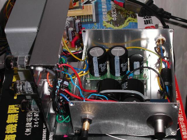
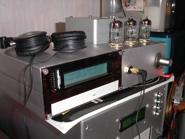
Similar to mine. My is with NFB (100K resistor from output to V1 grid to increase power to 32R headphones) and is using 6N2P (low current, high mu, like 12AX7, but 100% pinout compatible to ECC88) tube for V1, 110K for R2.Also I use 680uF 200V capacitors for output. What can I say, sounds very good (way better than chip amp I used before) and has not very low power to 32R phones and was made with tubes that are available to me")
Hi Pentium100,
No free lunch here. Realistically, you cannot expect such a design to really drive 32R phones - even a paralleled sections 6AS7 CF would have problems doing so, not speaking about the problems implied by the driver requirements.
For such severe loads (including my own Sennheiser HD595 at 50 ohms) I would prefer and suggest to build a "real" amp instead, as small as it might be output-wise.
Here is my own approach to drive to such severe loads (even small 8 ohms bookshelf speakers are no problem):
Toms headphone amp
Tom
Pentium100 said:Similar to mine. My is with NFB (100K resistor from output to V1 grid to increase power to 32R headphones)
No free lunch here. Realistically, you cannot expect such a design to really drive 32R phones - even a paralleled sections 6AS7 CF would have problems doing so, not speaking about the problems implied by the driver requirements.
For such severe loads (including my own Sennheiser HD595 at 50 ohms) I would prefer and suggest to build a "real" amp instead, as small as it might be output-wise.
Here is my own approach to drive to such severe loads (even small 8 ohms bookshelf speakers are no problem):
Toms headphone amp
Tom
Tubes4e4 said:Hi Pentium100,
No free lunch here. Realistically, you cannot expect such a design to really drive 32R phones - even a paralleled sections 6AS7 CF would have problems doing so, not speaking about the problems implied by the driver requirements.
Power is enogh for me for now (I use Philips SBC-HP200 headhones). 6AS7 would be better, I think, but I have one minor problem - I can't find 6AS7 anywhere (the same applies to all octal socket tubes, and most of power tubes, well, except EL84). If I had 6AS7 I would build amp for speakers instead.
I used this schematic http://headwize.com/images4/cmoy5_1c.gif but changed R2 to 120K after V1 (which was originally ECC88) died. I hadn't another ECC88, so I put 6N2P and changed R2.
Pentium100 said:Similar to mine. My is with NFB (100K resistor from output to V1 grid to increase power to 32R headphones) and is using 6N2P (low current, high mu, like 12AX7, but 100% pinout compatible to ECC88) tube for V1, 110K for R2.Also I use 680uF 200V capacitors for output. What can I say, sounds very good (way better than chip amp I used before) and has not very low power to 32R phones and was made with tubes that are available to me
Hi Pentium100
I want to using 6N2P in V1 and I don't want to change R2 to 110K. Is that possible?
- Status
- This old topic is closed. If you want to reopen this topic, contact a moderator using the "Report Post" button.
- Home
- Amplifiers
- Headphone Systems
- My new tube headphone amp