I'm wondering about making a small headphone amplifier from some bits and bobs i've got lying around unused... mostly BC546B's and MJE15032/33 and also some NE5534's. I figured I ought to be able to make something nice out of this lot.. possibly something Class A, maybe 1W into 32 ohms ?
I did already have a look around Headwize but most of those designs are for rather more expensive cans than my Beyerdynamic DT231's") I liked the Gilmore amplifier but that requires JFETs which are a complete pain to get, and expensive.
I liked the Gilmore amplifier but that requires JFETs which are a complete pain to get, and expensive.
Anyone got any suggestions?
I did already have a look around Headwize but most of those designs are for rather more expensive cans than my Beyerdynamic DT231's
I liked the Gilmore amplifier but that requires JFETs which are a complete pain to get, and expensive.Anyone got any suggestions?
Forgot I had this already on the forum. Should be just what you need Just make sure you keep the gain above 3 if you use NE5534 uncompensated.
http://www.diyaudio.com/forums/showthread.php?postid=492492#post492492
Just make sure you keep the gain above 3 if you use NE5534 uncompensated.http://www.diyaudio.com/forums/showthread.php?postid=492492#post492492
variations
This is similar to the previous circuit but illustrates a few other options
Even in a headamp extra current gain can be helpful, loads well within the rating reduce op amp gain, keeping the load high means the op amp is working less and distorting less
A single stage ef will give ~ 3 KOhm load on the op amp, cfp input impedance is another 100x higher
This cfp output circuit rolls off the power device drive at ~100KHz and I have biased the driver Qs relatively hot @ 20 mA to carry the high frequency out to the op amp gain intercept in the 300 MHz ft small signal Qs for low phase shift – just don’t expect this circuit to drive 100s of mA at 100s of KHz
Standard Vbe multiplier bias lets you trim the output bias current without having to find some exact odd low R value for the sense Rs
250 mA bias in a push-pull class A output lets you approach 500 mA load drive, ~ 3 W in to-220 requires some heat sinking but the clip-on type should be sufficient
The 5534 is an op amp that can be improved by output stage bias current, the bootstrap current source I’ve shown is set for ~ 4 mA – I would worry that something closer to 1 mA might not fully bias the output into class A, only very high resolution distortion measurements could let you find the optimum
This simulated circuit uses Lt1037 as a faster substitute for the 5534, if the circuit is stable with the Lt I’m pretty sure it should be ok with the 5534 – as a last resort you can add Ccomp to the 5534 between p5 & 8 (Cf is only a few pF to control peaking due to Op Amp input and stray C it needs tuning with a ‘scope)
For absolutely minimum distortion you could use an inverting circuit, but you would need to add a noise gain comp RC branch to stabilize it with the input disconnected and gain would be sensitive to source impedance
Attachments
Cool. I might refine it a bit by regulating the op-amp stage, but generally it looks sweet May I post a revised schematic here once done ?
EDIT: That was with reference to richie00boy's schematic - the revised one looks a bit more complex and uses parts I don't have to hand and Maplin probably won't have (because they suck).
I am thinking of adding a buffer stage using an OPA2134 I found in my parts box, with an Alps pot in the middle to act as a volume control though.
May I post a revised schematic here once done ?EDIT: That was with reference to richie00boy's schematic - the revised one looks a bit more complex and uses parts I don't have to hand and Maplin probably won't have (because they suck).
I am thinking of adding a buffer stage using an OPA2134 I found in my parts box, with an Alps pot in the middle to act as a volume control though.
my circuit was just thrown together in sim with spice models I already have to show some alternative circuit topologies
the Qs need only be generally similar, your mje15032/3 are a little large for this app but would probably work with the over conservative cfp local compensation I show
you should be able to mix and match the circuit elements - bjt current source, diode string bias, cfp...
the Qs need only be generally similar, your mje15032/3 are a little large for this app but would probably work with the over conservative cfp local compensation I show
you should be able to mix and match the circuit elements - bjt current source, diode string bias, cfp...
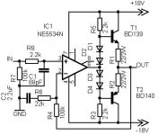
Here is my headphone amplifier. It can drive 8ohms loudspeaker, with about 1W. You can use any kind of output device, even MJE15032/33, with higher bias, for class A solution.
Put D1, and D4 to the heatsink of the output devices to get some thermal compensation. Gain is about 6
sajti
Put D1, and D4 to the heatsink of the output devices to get some thermal compensation. Gain is about 6
sajti
Attachments
- Status
- This old topic is closed. If you want to reopen this topic, contact a moderator using the "Report Post" button.
- Home
- Amplifiers
- Headphone Systems
- Headphone amplifiers?