I'm not too worried about EQ at the moment -- otherwise I'd never get it finished. I'm keeping my fingers crossed that they will be less sibilant.
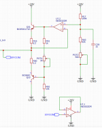
New 10V virtual ground.
A lopsided 4:1 emitter resistor ratio seems to improve distortion a bit, probably because the control is also a bit lopsided.
Bias set to about 1.5mA (1k + POT4 = 2.2k).
1V sine through 125 ohms produced a +/-1.4uV sine offset with only 0.4% THD (referenced to H1 = 1.4uV).
New 10V virtual ground.
A lopsided 4:1 emitter resistor ratio seems to improve distortion a bit, probably because the control is also a bit lopsided.
Bias set to about 1.5mA (1k + POT4 = 2.2k).
1V sine through 125 ohms produced a +/-1.4uV sine offset with only 0.4% THD (referenced to H1 = 1.4uV).
Attachments
At 1.4uV total including the fundamental vs 1,000,000uV signal level, I don't think it matters.
The simulator used a NE5534 model which might have slightly higher gain than the NE5532 that I actually want to use, but it's still nice and slow. I haven't checked the PSRR, but the 20V rail is already regulated.
I may change the pot to 2 parallel thin film resistors.
The simulator used a NE5534 model which might have slightly higher gain than the NE5532 that I actually want to use, but it's still nice and slow. I haven't checked the PSRR, but the 20V rail is already regulated.
I may change the pot to 2 parallel thin film resistors.
The prototype PCB is now in production. Can't wait!
Too many cool things on it for something not to go wrong in the beginning, but we shall see.
I might re-purpose my post/s on the first page to add updates to keep things organised.
Recapping:
Topology:
Single Ended class-A.
First stage: open drain JFET with resistor pull-up and low-pass filtering of the +ve power supply rail.
2nd stage: open drain MOSFET with a 2-stage JFET+PNP constant current source. A 2-stage CCS seemed to give the best of both worlds with the JFET having good distortion matching and the superior ripple rejection of the PNP.
DC coupled:
Instead of a 470u-1000uF output capacitor, together with its self-defeating leakage current and DC offset, the design uses a virtual ground at around 10-12V (adjustable). Maximum simplicity with an NE5532 op-amp boosted with a push-pull PNP-NPN output stage. 1uV ripple vs 1V signal level should be inaudible.
Servo:
A subsonic filtered feedback amplifier (servo) compares the audio output against the virtual ground, and provides local feedback to the MOSFET. Apart from the servo, which has very low gain at audio frequencies, the design relies entirely on emitter degeneration.
It seems to have a lot of stuff for something that is basically:
INPUT-->capacitor-->JFET-->capacitor-->MOSFET --> headphone --> v.ground.

PSU
SMPS with 5V to 24V boost.
Instead of developing a dual PSU, where I would have to consider ripple on both rails, everything is ground referenced.
Anti-thump circuit:
An LPC804 microprocessor monitors voltage levels with resistor dividers and triggers a dual-coil relay. I specifically wanted to avoid wasting power with a "normally off" relay. And the logistics hot-unplugging is still a bit up in the air, but I don't want to do everything at once. The coils can be fired manually so I can start listening while still writing the firmware.
Too many cool things on it for something not to go wrong in the beginning, but we shall see.
I might re-purpose my post/s on the first page to add updates to keep things organised.
Recapping:
Topology:
Single Ended class-A.
First stage: open drain JFET with resistor pull-up and low-pass filtering of the +ve power supply rail.
2nd stage: open drain MOSFET with a 2-stage JFET+PNP constant current source. A 2-stage CCS seemed to give the best of both worlds with the JFET having good distortion matching and the superior ripple rejection of the PNP.
DC coupled:
Instead of a 470u-1000uF output capacitor, together with its self-defeating leakage current and DC offset, the design uses a virtual ground at around 10-12V (adjustable). Maximum simplicity with an NE5532 op-amp boosted with a push-pull PNP-NPN output stage. 1uV ripple vs 1V signal level should be inaudible.
Servo:
A subsonic filtered feedback amplifier (servo) compares the audio output against the virtual ground, and provides local feedback to the MOSFET. Apart from the servo, which has very low gain at audio frequencies, the design relies entirely on emitter degeneration.
It seems to have a lot of stuff for something that is basically:
INPUT-->capacitor-->JFET-->capacitor-->MOSFET --> headphone --> v.ground.
PSU
SMPS with 5V to 24V boost.
Instead of developing a dual PSU, where I would have to consider ripple on both rails, everything is ground referenced.
Anti-thump circuit:
An LPC804 microprocessor monitors voltage levels with resistor dividers and triggers a dual-coil relay. I specifically wanted to avoid wasting power with a "normally off" relay. And the logistics hot-unplugging is still a bit up in the air, but I don't want to do everything at once. The coils can be fired manually so I can start listening while still writing the firmware.
Attachments
Schematic
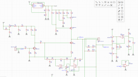
Schematic of left channel, not including page 2, which contains various peripherals like the 5V to 24V boost SMPS, dual coil relay or MCU.
After playing around some more with simulation values, I will start off with R4 = 5.6k, for a bias current of about 12mA.
R10 + R11 ratio will be a little higher to attempt to squeeze 22V out of the LM317.
The drop-out may be little high if the input is exactly 24V, but we shall see.
I could've filtered the RHS so that the op-amp and the output stage of the V-GND in particular doesn't modulate the 20-22V positive rail. But the input stage is already hardened against line noise. Only the output stage maybe susceptible to modulation, but that's what the LM317 is for, anyway.
Attachments
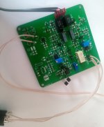
Freshly built. I'll try and put up a few pics and do more tests in the coming days.
The push-pull v-ground was too simple again, and goes into thermal runaway, which I haven't fully analysed yet. That'll learn me to cut corners
It really needs a more stable design with a couple of diodes between the NPN and PNP bases.
Meanwhile, I did a simulation running a signal in reverse to modulate the v-ground and found that the main output stage followed it much better than I expected. Amplitude vs frequency plots across the headphone load showed a plateau of to 50-55dB of attenuation in the 100Hz - low kHz range. The output impedance was reduced in the sub-bass due to voltage feedback from the servo, and also at high frequencies but I'm not sure why just yet for the latter.
Just finished soldering earlier today.
There was a bit of debugging at first --accidentally ordered large SO-8 op-amps for the servos instead of slightly smaller SOIC-8, so that was fun. But once that was fixed, it was a matter of turning the pots to get the offset to within a single mV, according to the Volt meter.
Listening impressions...
Volume:
Very more-ish. My ears ran out of power before the amp did, and for the sake of experiment I just kept turning the volume up and up to what started to feel like live levels.
It seems to thrive on everything including some complex stuff like Japanese melodic rock (Wagakki band, Senbonsakura).
Lows: slightly warm mid-bass as expected, but not overpowering. Tonally warm but not symphonic. Kick drums deliver kick without obscuring anything and give an impression of being really 'fast'.
Highs:
My DT-880's have always been a bit 'hot', but sybilants sound like they have been moved up in frequency and smoothed out, and 'hash' removed. Esses are cleaner, and the entire mid range is a lot cleaner and sharper - and that's all just running from the same smart-phone source.
Really happy overall. The EQ is probably a little U-shaped, but not sure if it's worth bothering about for now.
There was a bit of debugging at first --accidentally ordered large SO-8 op-amps for the servos instead of slightly smaller SOIC-8, so that was fun
. But once that was fixed, it was a matter of turning the pots to get the offset to within a single mV, according to the Volt meter.Listening impressions...
Volume:
Very more-ish. My ears ran out of power before the amp did, and for the sake of experiment I just kept turning the volume up and up to what started to feel like live levels.
It seems to thrive on everything including some complex stuff like Japanese melodic rock (Wagakki band, Senbonsakura).
Lows: slightly warm mid-bass as expected, but not overpowering. Tonally warm but not symphonic. Kick drums deliver kick without obscuring anything and give an impression of being really 'fast'.
Highs:
My DT-880's have always been a bit 'hot', but sybilants sound like they have been moved up in frequency and smoothed out, and 'hash' removed. Esses are cleaner, and the entire mid range is a lot cleaner and sharper - and that's all just running from the same smart-phone source.
Really happy overall. The EQ is probably a little U-shaped, but not sure if it's worth bothering about for now.
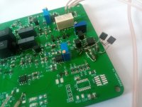
The mods look a bit brutal, but they work
Mods:
2 BC546's as high-performance diode drops + 100 ohm between the bases in the push-pull virtual ground.
Through-hole J113 and J175 JFETs because the surface mount MMBF versions were all out of stock :'(
24V plugged in directly (boost converter out of stock LOL.)
TO-DO's:
LPC804 ARM MCU to control the latching relay. The relay works BTW, when 5V is connected, thanks to the 2-pin headers that can be easily shorted with tweezers to switch it one way or the other.
The 3.5mm stereo jack is AWESOME with a really hard click and sense springs that allow additional circuitry to detect if something is plugged in or not. I may use this feature with the input in particular. At the moment, hot-plugging the source while wearing headphones is a bit like getting unplugged from the Matrix, and that should be fixable.
New PSU design that either uses 24V directly from a generic wall transformer, or new USB-style boost converter. TBH, I wasn't too impressed when wading through USB specs, so I may just use the KISS principle.
Attachments
After a couple of days of listening, it sounds really good to my ears.
I'm wondering if I should reduce the 220 ohm source resistor to around 100 ~ 47 ohm. THD sims much higher, but the harmonic profile looks 'better', with a significantly reduced string of 5+ harmonics, at the cost of a raised 2nd harmonic.
Gain is already high and with sources like a laptop or phone, a bit of processor noise comes through on the built-in sound card DAC. So I would also reduce gain on the input JFET.
At 47 ohms, op-amp current would also have to be increased so it doesn't hit the bottom rail.
- Home
- Amplifiers
- Headphone Systems
- Current drive headphone amp in the works