That's a serious headphone amp. Thanks for sharing.
Thanks, William.
My friend had a first listen last night. He will probably reveal himself here at some point. His comment was that the amplifier sounds quiet and clean but slightly dry and etched compared to the DCG3.
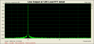
The DCG3 has a second-order dominant distortion (FFT courtesy of Salas in the DCG3 thread) and this is into a 1.5K load. My friend is using 26 Ohm Oppo planar headphones so presumably the current demand, and resulting distortion, are higher than shown on the graph.
I've decided to call this amp the HPA1 since it's a headphone amp and my initials are "HP." So, my impression of the difference between the HPA1 and the DCG3 is that it's like the stereotypical difference between tube and transistor sound. In my advancing old age, I don't have much in the way of top-octave hearing, so I may be missing some distortion that others would readily detect. Or it could be a matter of preferring a slightly more or less colored sound.
Being based on the Blameless topology, this amp might sound like one of those amps. People who don't like the Blameless tend to call it dry and uninvolving. It's hard to define a reference, especially with headphones. The point of the exercise is to try different topologies and see how they sound. I could really use an Audio Precision analyzer right now.
In other news, just in the past couple of weeks, more key parts for this design have gone out of stock at the usual suspects. This may push me to move forward with SMD for continued development of the circuit.
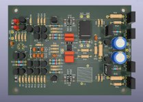
I've uploaded my KiCad project files for the amplifier board to Dropbox. Send me a PM if you would like a link.
Attachments
Last edited:
Nice boards. I don't recall reading about this design. I'll look it up.
I think Talema must be struggling with COVID because many of their encapsulated transformers are out of stock at Digi-Key. I lucked out and found the same 15-0-15V transformers with RS labeling on the RS Exports website in England. They were actually cheaper than Digi-Key and arrived in the same amount of time. But the other day I got an email from RS Exports saying they won't do any more business with me until I supply them with a tax exemption certificate.
Not only transformers: Mouser has run out of bloody 2.54 mm Molex connectors, the most common, ordinary things one can imagine. NE5532s? In yer dreams, buddy. Even 115-230 volt slide switches won't show up until January 2022.
I've been playing with SPICE and learning more about advanced compensation techniques. Something I failed to appreciate during the design of the amp in this thread is how sensitive the VAS collector-to-base circuit is to tiny capacitances, on the order of 1 pF.
It looks like, from SPICE, that the Baker clamp diode I added has significantly buggered the compensation. It turns two-pole compensation into three-pole compensation, and presumably it's highly-dependent on diode junction capacitance nonlinearity since it's not swamped by a large Cdom. Consequently, I decided to toss the Baker clamp. I added a 1K base current-limiting resistor to the VAS transistor. This doesn't stop saturation, but it keeps the transistor from blowing. SPICE doesn't simulate saturation well, so I won't know how bad the clipping is until I try it in real life.
Adding back-to-back diodes across the LTP cascodes further reduces the amount of VAS base current during overload. This should speed up recovery. The cost is a small increase in distortion.
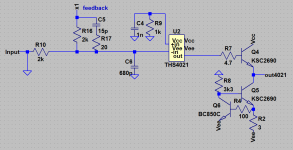
I also learned this week about putting a Zobel from the input of the diamond buffer to ground to compensate for the diamond's natural RF peaking. I selected 10 Ohms and 390 pF for this.
I was able to retune the TPC with smaller capacitors which reduces the load on the VAS output. The overall effect is a, well, a significant decrease in simulated distortion, more gain margin, higher open-loop GBW, and no loss of phase margin.
My amp is still out for evaluation. The assessment is overall very good, but with a complaint about tonal balance. I have to wonder if all this has anything to do with the subjective performance. I don't have a function generator to do square wave testing, but I plan to get one shortly. When I get the amp back, I will do some more testing, then take it apart and modify it to make these changes. If I'm pleased with the results, I will update the design.
It looks like, from SPICE, that the Baker clamp diode I added has significantly buggered the compensation. It turns two-pole compensation into three-pole compensation, and presumably it's highly-dependent on diode junction capacitance nonlinearity since it's not swamped by a large Cdom. Consequently, I decided to toss the Baker clamp. I added a 1K base current-limiting resistor to the VAS transistor. This doesn't stop saturation, but it keeps the transistor from blowing. SPICE doesn't simulate saturation well, so I won't know how bad the clipping is until I try it in real life.
Adding back-to-back diodes across the LTP cascodes further reduces the amount of VAS base current during overload. This should speed up recovery. The cost is a small increase in distortion.
I also learned this week about putting a Zobel from the input of the diamond buffer to ground to compensate for the diamond's natural RF peaking. I selected 10 Ohms and 390 pF for this.
I was able to retune the TPC with smaller capacitors which reduces the load on the VAS output. The overall effect is a, well, a significant decrease in simulated distortion, more gain margin, higher open-loop GBW, and no loss of phase margin.
My amp is still out for evaluation. The assessment is overall very good, but with a complaint about tonal balance. I have to wonder if all this has anything to do with the subjective performance. I don't have a function generator to do square wave testing, but I plan to get one shortly. When I get the amp back, I will do some more testing, then take it apart and modify it to make these changes. If I'm pleased with the results, I will update the design.
Attachments
Here are a couple of superb papers that derive the equations for two-pole compensation:
https://www.researchgate.net/profil...e-Compensation-in-Linear-Audio-Amplifiers.pdf
https://www.electronicsworld.co.uk/wp-content/uploads/2020/04/amps.pdf
The second paper, which is quite long, goes on to compare the Thompson (Blameless) topology to some alternatives, concluding that Thompson "has yet to be superseded in any substantive way." Interesting reading.
The low-distortion-at-all-costs crowd strongly condemn Baker clamps across the VAS and SPICE confirms the negative effect. I don't have a sense whether 0.000004% of added distortion is a problem in real life.
One other issue I've noticed is a weird phase inversion (see attached) on negative peaks that happens when I drive the amplifier strongly at RF frequencies. It should be possible to protect the amplifier from slewing or overload at any frequency when the input amplitude is limited to normal levels. I may have just overloaded the input with my generator. This misbehavior should not be a problem in real-world use, but I need to investigate more. SPICE does not show this effect.
I've been working on a new design based on Cordell's error-correcting MOSFET amplifier paper (http://www.cordellaudio.com/papers/MOSFET_Power_Amp.pdf). The VAS in this design is naturally current-limited. The driver uses clamps but they are referenced to a fixed voltage so don't suffer from Miller-bootstrapping the junction capacitance.
The other day, I ordered some KSC2690/KSA1220 pairs from eBay. These are TO-126 devices, but three times faster than the D44/45H11 devices I use as outputs. Their power dissipation is only 20W, but they ought to suffice with adequate heat sinking and/or moderate bias current reduction. Having faster output transistors makes it easier to hit phase/gain margin targets without excessive compensation.
I'd like to swap the TTA/TTC004Bs for KSA1381/KSC3503s. Alas, while the KSA1381E is readily available, KSC3503s are only sold in D grade and the matching higher-spec parts are gone forever from any reputable supplier I can find.
It might be possible to do away with the TTA/TTCs entirely and use TO-92s here. For bias tracking, you'd like the diamond drivers to be thermally coupled to the outputs somehow.
My friend who is evaluating the amplifier is a well-known diyaudio.com member. There is probably no need to hide his identity, and he has promised to post here eventually, but I prefer not to name him until he's ready to come out of the woodwork.
Emailing with him yesterday, his main observation is dryness in the midrange compared to the DCG3. He's still trying to figure out whether this is a fault of the amplifier, a synergy thing with his low-impedance planar headphones, a matter of equalization, or just a personal preference. He is a single-ended triode guy which says something about his taste. Personally, I like the way the HPA1 (now my official name for the project) cleans up the midrange compared to the DCG3.
One thing I want to emphasize is that this is still a prototype. I believe the amplifier works well as shown, but caution anyone who wants to duplicate it that the design hasn't been fully tested nor tuned for sound quality in any way.
Attachments
Very nice!
Thanks.
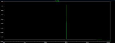
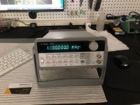
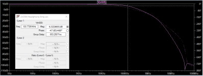
I forgot to mention, the frequency in the photo above is 5 MHz.
Also, the output inductors are 14 turns of magnet wire wound on a 3/8" drill bit. After heat shrinking the coils, I smeared some epoxy inside to hold things together. Unfortunately, the spools in my junk box are unlabeled, but the wire diameter looks to be about 0.7mm. The value isn't critical. I measured mine around 1.2 uH or so, IIRC.
Attachments

Thank you for the ongoing useful information. I look forward to future developments
Again, thanks for the positive feedback. I worry that many of these details could be more information than people want to read. On the other hand, I know people have different levels of technical background/interest, and maybe enough are interested that it's worth the effort.
A lot of this is very subtle and I spend hours reading and thinking, trying to develop my technical intuition. I believe there's a need for articles and discussion that bridge the gap between generalities (like, "Feedback through Cdom linearizes the VAS") and pages of math. I feel I would succeed if I could turn a complicated mathematical idea into something more accessible to math-challenged readers (like myself). But you can only make complicated things so simple.
Later, I may try to write down what I've learned about the theory and advantages of two-pole compensation. I may earn a fortune with a novel insomnia cure.
a child could do it short - YouTube
I said I would write some notes on two-pole compensation, and I've tried a couple of times. But I keep getting off onto long-winded essays that seem inappropriate, so I will just say a few brief things and if anyone wants to discuss it, I will be happy to say more.
I didn't understand TPC until recently and was pleasantly surprised to find it's not as scary as I expected. I was even more surprised how well it worked out in HPA1. The big advantages seem to outweigh the small disadvantages, and now I intend to use TPC (or some other advanced compensation) in my designs going forward.
I posted above some good papers on TPC, but here is a very short summary. Compensation is a race to roll off the loop gain below unity before the phase shift hits 180 degrees (120-135 degrees in practice). With TPC, we start the rolloff faster and later, then back off at the end so we cross the finish line with an adequate phase margin. The downside is the loop phase dips close to -180 degrees at midband. But Nyquist tells us this is ok, provided the phase picks back again near the unity gain point.
In principle, the reduced phase margin at middle frequencies isn't a problem, but clipping or large-signal parameter changes can make the amplifier conditionally unstable. TPC amplifiers seem to behave worse when clipping, and I saw that with my design.
The benefit is much more area between the open- and closed-loop gain curves, which translates to more feedback available for error correction. So, all other things being equal, the amplifier with TPC can have much lower distortion across the band, instead of just at low frequencies as is the case with dominant pole compensation.
There is another benefit, and it is huge. The dominant pole capacitor looks like a short circuit to the input stage at most frequencies. This is because its reactance is negative-bootstrapped (Miller effect) by the voltage gain of the second stage. With TPC, we reduce the amount of feedback around the VAS. Less shunt feedback means the VAS input impedance is higher, and much less current is demanded from the input stage. This has a whole slew (pun intended maybe?) of advantages including reduced IPS distortion.
The VAS doesn't have to swing that much current compared to the output stage, and can be designed for adequate linearity. The total amount of gain in the system remains fixed, but by throwing away less gain with local feedback around the VAS, we can wrap the output stage in more feedback, to good effect overall.
There are two capacitors and one resistor in the TPC network, and the values have to be selected. A formula that seems to work is as follows:
1) Start by making the value of the capacitor connected to the VAS output the same as you would use for dominant-pole compensation.
2) Make the second capacitor ten times this value.
3) Using SPICE, adjust the value of the resistor for a good compromise between phase margin, gain margin, and available negative feedback at midband.
The loop gain will show some peaking at the lower corner frequency. Playing in SPICE, you can get an idea of the effect of varying the values of each component. You can get rid of the peak by implementing three-pole compensation. You do this by adding a third capacitor in series with the resistor. 150nF is a good starting point. Then you spend some time iterating in SPICE and hope your models are accurate. I haven't tried three-pole compensation yet, but plan to in my next design.
As I said earlier, a very small capacitor (1-2 pF) across the whole network completely alters the response. This is in the range of the capacitance of a switching diode, so a Baker clamp from collector to base will mess things up considerably.
You an still get a decent response with the clamp diode in place (New Headphone Amplifier Design) but it doesn't look like the curves you'll see in the textbook examples. This is where I'm at right now with HPA1 and it does seem to work. HPA2 will have a different clamping scheme to avoid this problem.
Feedback theory can get pretty complicated pretty fast, to the point where it makes my brain hurt and I would rather look at Netflix than do math. Buried in this (https://www.diyaudio.com/forums/solid-state/243481-200w-mosfet-cfa-amp.html)) thread are some highly technical discussions that seem very interesting but I haven't had the mental fortitude to digest the information yet.
Anyway, that seems like more than enough for a "brief" posting.
As always, FWIW and YMMV.
Feedback theory can get pretty complicated pretty fast, to the point where it makes my brain hurt
Yup.
It’s hopeless to turn off this road as soon as you embark on it. These are the hard drugs of the audio world.
How much feedback depth you can cope with?
I'm not sure I want to mess with fifth-order feedback! Too advanced for me, and maybe it's more an intellectual curiosity than a practical necessity.
My next research project is to digest Middlebrook's paper on the General Feedback Theorem. I have an EE diploma in a drawer somewhere, but that was from forty years ago and my brain isn't getting any younger. I was never good at math anyway, but got by on my intuition.
I'm about ready to order boards for HPA2. I may start another thread for that.
Attachments
I'm not sure I want to mess with fifth-order feedback! Too advanced for me, and maybe it's more an intellectual curiosity than a practical necessity.
Yes. Not so easy, but very curious.
My next research project is to digest Middlebrook's paper on the General Feedback Theorem. I have an EE diploma in a drawer somewhere, but that was from forty years ago and my brain isn't getting any younger. I was never good at math anyway, but got by on my intuition.
You can start from there:
http://www.ti.com/lit/an/sboa015/sboa015.pdf
https://www.ti.com/lit/pdf/slyt174
I'm about ready to order boards for HPA2. I may start another thread for that.
Why don't you try something like simple bruteforce?
Attachments
Thanks for the links. The first TI paper is nice, and easy enough that I don't have to break my brain to read it. I will spend some time on it later.
I ordered a lot of obsolete transistors recently (my kids will throw them in my casket) and am in a phase now exploring whether complicated discrete designs sound good. I plan to build an op-amp circuit at some point for comparison, but I know I'm not alone in saying, "Where's the fun in that?" Eight-legged fuses, LOL.
My signal generator came last week, and I have to get HPA1 back so I can do some more testing. I probably should have bought the Siglent, but I have six (now seven) pieces of HP test gear on my bench and I'm a sucker for old things.
Attachments
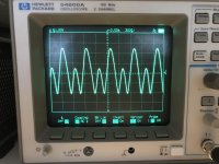
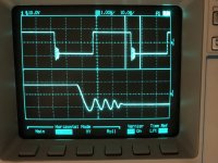
I got my amplifier back this evening and did a few quick tests. Everything looks good in general, with one issue (first picture). The input signal is a square wave at 20 kHz. Output level is about 15V pk-pk. Load resistance is 50 Ohms, and the volume control is full open. You can see there is some ringing on the falling edges. If you set the function generator level just right, the oscillation will continue for the duration of the negative part of the wave, and a little beyond.
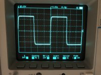
The second picture shows the output with the volume control backed off one click. I turned up the signal generator so the amp was just below clipping, 24V pk-pk. Looks good.
The ultrasonic input filter bandwidth varies with the volume setting. Best-case bandwidth is over 1 MHz, so I can experiment with more aggressive input filtering. The amplifier will never have to contend with such severe overdrive in the real world, but it would be nice if it could handle it without overloading. I'll look into it in my copious free time.
I'm listening to it now; sounds great.
-Henry
Attachments
SPICE pretty accurately predicts the input stage overloading with a large enough square wave signal. It has to have a sharp edge. I didn't realize until last night that you need to specify the rise and fall times explicitly in LTspice, or it defaults to a very long/slow value.
The simulation shows that falling edges overload first as you turn up the input amplitude. It takes a little more signal level to overload on rising edges, which I also saw in my bench test. SPICE shows some overshoot, but not outright oscillation. That's not too surprising.
You can always overload the input stage if you drive it hard enough. I would like the amplifier to be protected from slewing when driven to clipping output level by a square wave, at all input volumes. It looks like increasing the input filter capacitor from 56pF to 100pF will do this.
Otherwise, try not to listen to source material with a slew rate greater than 250 V/uS at the input to the amplifier.
try not to listen to source material with a slew rate greater than 250 V/uS at the input to the amplifier.
SPICE shows some overshoot, but not outright oscillation.
Feel free to listen an amp with slightly different compensation capacitors values and corresponding overshoot. And, of course, different onboard rail capacitors.
This is the most hearable factors for slightly tuning music reproduction.
Feel free to listen an amp with slightly different compensation capacitors values and corresponding overshoot. And, of course, different onboard rail capacitors.
This is the most hearable factors for slightly tuning music reproduction.
I agree. Under normal conditions, there's no overshoot, as shown in the second picture I posted earlier. I think the oscillation is due to TPC's narrow midband phase margin, and the amplifier loop gain dropping during overload. It seems to be one of the tradeoffs of TPC.
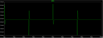
The first picture below shows the simulated current in the input transistor with the existing filter (3.3K/56pF) and a +-2.5V square wave input. You can see it's just cutting off on the falling edge. I'm impressed how closely the simulation matches the onset of instability in the real-world amplifier, though it might be a coincidence.
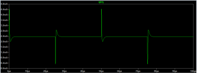
The second picture shows the same thing but with the capacitor increased to 120F. This is enough to keep the amplifier from overloading even if I then raise the input level to +-4V.
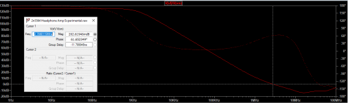
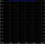
The third picture shows the worst-case bandwidth of 130 kHz with the 120pF capacitor and the volume control set to -6dB (effective series resistance 5K Ohms). I'm reminded of W. Marshall Leach's comment in his 1976 "Build a Low-TIM Amplifier" article:
For those who can psychologically accept an amplifier which is 3dB down at 50 kHz...
I posted earlier some ideas I had about improving the circuit. I'm really happy with how it sounds right now and it looks nice so I'm reluctant to tear it apart immediately. I'm not sure how important it is to tune the amplifier to withstand massive input signal overloads without glitching.
Attachments
On further investigation in SPICE, it looks like the input overload margin can be improved a bit by increasing the capacitor across the 2K feedback resistor from 10pF to 33pF. The tradeoff is a little lower gain margin. The output inductor appears effective at preventing oscillation with a capacitor across the load resistor.
Edit: I think I'm going to call this design "done" and move onto other projects.
Edit: I think I'm going to call this design "done" and move onto other projects.
Sure, thanks for asking.
Over the winter, I decided to build Salas' DCG3. I designed a PC board roughly following the official layout, and also designed a power supply board based on the Super Regulator schematic. This was my first experience with "real" headphone systems. It came out really well and I ended up building another, which I sold to a friend. He described it as "The best headphone amplifier I have heard," which is a testament to Salas' design skill more than my construction ability.
After finishing those projects, I was reading the Wolverine amplifier thread on the solid-state forum, and also reading Douglas Self's book. The DCG3 circuit is relatively simple for a discrete op-amp. I started wondering whether adding more bells and whistles to the circuit would make things better, worse, or indifferent. The goal was to try something very conventional and boring as a reference point for future projects that might be more original.
What I came up with is a standard Blameless front end mated to a Class A diamond buffer output stage. I cribbed Salas' DC servo circuit from the DCG3 and powered it with another copy of my Super Regulator board.
I have a delay circuit I designed that operates the DCG3 muting relay and also switches a bi-color power indicator LED. I didn't have parts to make one of these, so I decided just to run the relays with a battery and a switch. Unfortunately, the switch I bought Saturday turned out to be momentary contact, so I have to wait until Monday to buy a new one.
I will follow up with more information in a second post.
About Diamond Buffer variations:
https://www.diyaudio.com/forums/solid-state/378269-diamond-buffer-variations.html#post6817544
Advantages and disadvantages?
- Home
- Amplifiers
- Headphone Systems
- New Headphone Amplifier Design