Hi everyone,
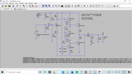
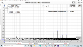
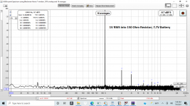
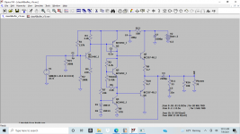
This is a basic 9V battery-powered buffer I have been playing with on the breadboard, as I am trying to learn more about discrete circuit design. I know something about electronics but not a lot, and this is the first project where I am thinking about things like thermal and electrical stability. The schematic and LTSpice model are attached. The output stage is biased at about 5.5 mA in order to give 26 mV across R9. Two channels then draw 14-15 mA so may be suitable for some portable applications. I have attached measurements (made using REW and a Scarlett Solo) of distortion for a 1V RMS 1 kHz signal into 33 and 150 Ohm resistors, which both happen to show THD of 0.0013%. At 20 kHz that rises to about 0.02% (using 192 kHz sample rate). Likewise the SMPTE IMD measurement for 1V RMS into 33 Ohms seems reasonable.
For some context, it will be used to buffer cross-feed circuits and will drive my Grado SR-80e and AKG K553 Pro headphones, both of which are 32 Ohm and 114-115 dB / 1V RMS. I listen at about 70-75 dB so 100 mV is plenty of voltage drive for me right now, but in order to be useful (at least for me) for many 'typical' headphones the goal is good performance up to 1V RMS. I realize that this buffer is more limited than almost all of the other projects here, but perhaps it might be interesting to others who only need 1 Volt or so.
While it seems to work well, the primary uncertainty for me is electrical stability. The compensation capacitor was chosen via LTSpice and according to predictions should give at least 50 degrees of phase margin and 9 dB of gain margin for 16-300 Ohm resistors in parallel with 3 nF. I have done a number of measurements (square wave, frequency response, spectrum during operation, checking current draw and whether components get warm during normal operation, etc) and it seems fine driving actual headphones, but my digital scope only goes to 10 MHz and my signal generator is limited to 100 kHz, so I don't feel like I can definitively claim much about electrical stability. It definitely is thermally stable, though.
Anyway, since I am not an expert I suspect that I made some rookie choices / mistakes, and would welcome any suggestions for improvement. I'd rather try changing things prior to soldering it up than after!
Thanks,
Jason
Attachments

The Zobel network should have a resistor that matches the amp's expected load, ie 33 ohms, ideally(*), probably not at all critical though.
The power should come in from the RHS, and its wise to have a low pass filter on the rail after the power output stage to prevent unwanted feedback via the rail to the input stage, perhaps 100ohm and 100uF.
(*) The function of the network is so the amp sees a fairly constant resistive impedance across a wide frequency range, even if the load is inductive.
Hi Mark,
I have updated the schematic - is this what you are meaning?
The Zobel is one of the design choices I was not at all sure about, so this helps. I changed the capacitor as well to keep the transition frequency in the ballpark of 150 kHz, if that makes sense.
I didn't know that the power should come in from the right, and the idea of filtering makes sense now that you say it! This is also consistent with my experience with the breadboard. When I first measured the distortion the 2nd and 4th harmonics were at least 20 dB higher. Simply moving the location where the battery connected to the breadboard to be right near the output solved much of the problem. Fiddling with the location of the power supply capacitor made the rest of the improvement and made the measurements sufficiently close to the simulations that I stopped fiddling. But it was all trial and error and did make me concerned about layout.
Tonight I will make the changes on the breadboard and see how it goes.
Thanks!
Jason
Attachments
This thread is super-stale but in case folks are interested I did make a pcb for this (my first ever, so it probably isn't so great) and use it regularly. Over a year ago I wrote on the headphone amp photo gallery thread that I would post the gerbers but never did - it is probably too late but here they are. First, here is the schematics with the part numbers from the pcb:

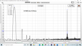
I used a Scarlett Solo and REW to measure distortion. Here are 1 kHz results into 33 Ohms for 200mV RMS

and at 1V rms into 33 Ohms:

Overall I am pretty happy with the result.
Note each board is just one channel - I did it that way since I ordered from a place that charges by the square inch and you get multiple boards. You can see the populated boards at
https://www.diyaudio.com/community/threads/headphone-amp-photo-gallery.366591/page-4#post-7013205
Cheers,
Jason
PS. Some relevant sizes are
C3: output capacitors are 10mm diameter, 5mm pitch
C5: 8mm diameter, 3.8mm pitch
C1: 5mm pitch
I used a Scarlett Solo and REW to measure distortion. Here are 1 kHz results into 33 Ohms for 200mV RMS
and at 1V rms into 33 Ohms:
Overall I am pretty happy with the result.
Note each board is just one channel - I did it that way since I ordered from a place that charges by the square inch and you get multiple boards. You can see the populated boards at
https://www.diyaudio.com/community/threads/headphone-amp-photo-gallery.366591/page-4#post-7013205
Cheers,
Jason
PS. Some relevant sizes are
C3: output capacitors are 10mm diameter, 5mm pitch
C5: 8mm diameter, 3.8mm pitch
C1: 5mm pitch